Power transmission device and electronic instrument

a technology of power transmission device and electronic instrument, which is applied in the direction of pulse generator, pulse technique, pulse train generator, etc., can solve the problem that the power circuit of the power transmission device cannot be appropriately controlled

Inactive Publication Date: 2008-11-27
SEIKO EPSON CORP
View PDF5 Cites 27 Cited by
  • Summary
  • Abstract
  • Description
  • Claims
  • Application Information

AI Technical Summary

Benefits of technology

[0015]the resonant capacitor being disposed in a second row position between the first row position where the first coil connection terminal and the second coil connection terminal are disposed and a row position where the control IC is disposed;

Problems solved by technology

Therefore, the power circuit of the power transmission device cannot be appropriately controlled without reducing an adverse effect due to a large analog current.

Method used


Image

  • Power transmission device and electronic instrument
  • Power transmission device and electronic instrument
  • Power transmission device and electronic instrument

Examples


Embodiment Construction

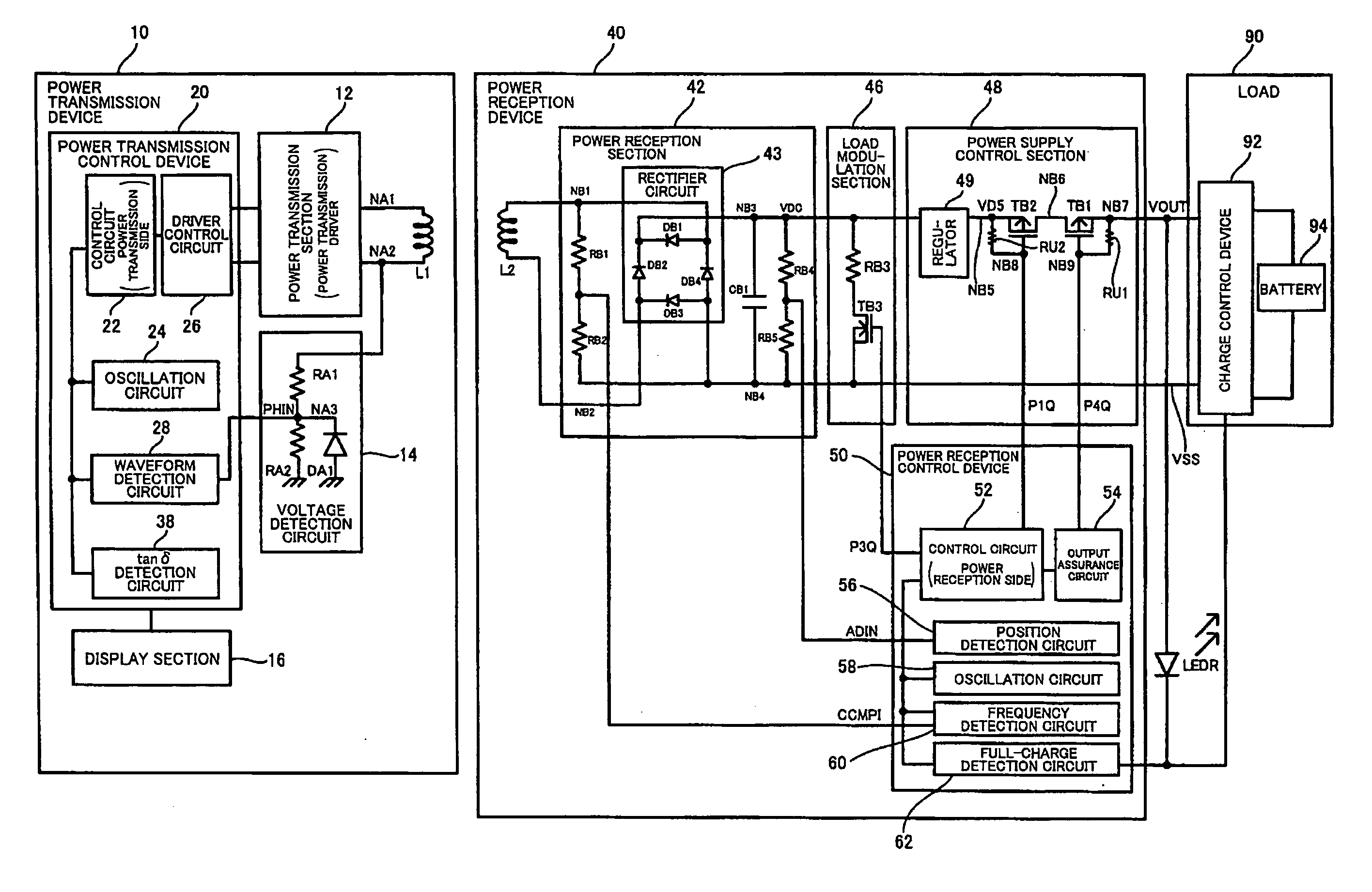
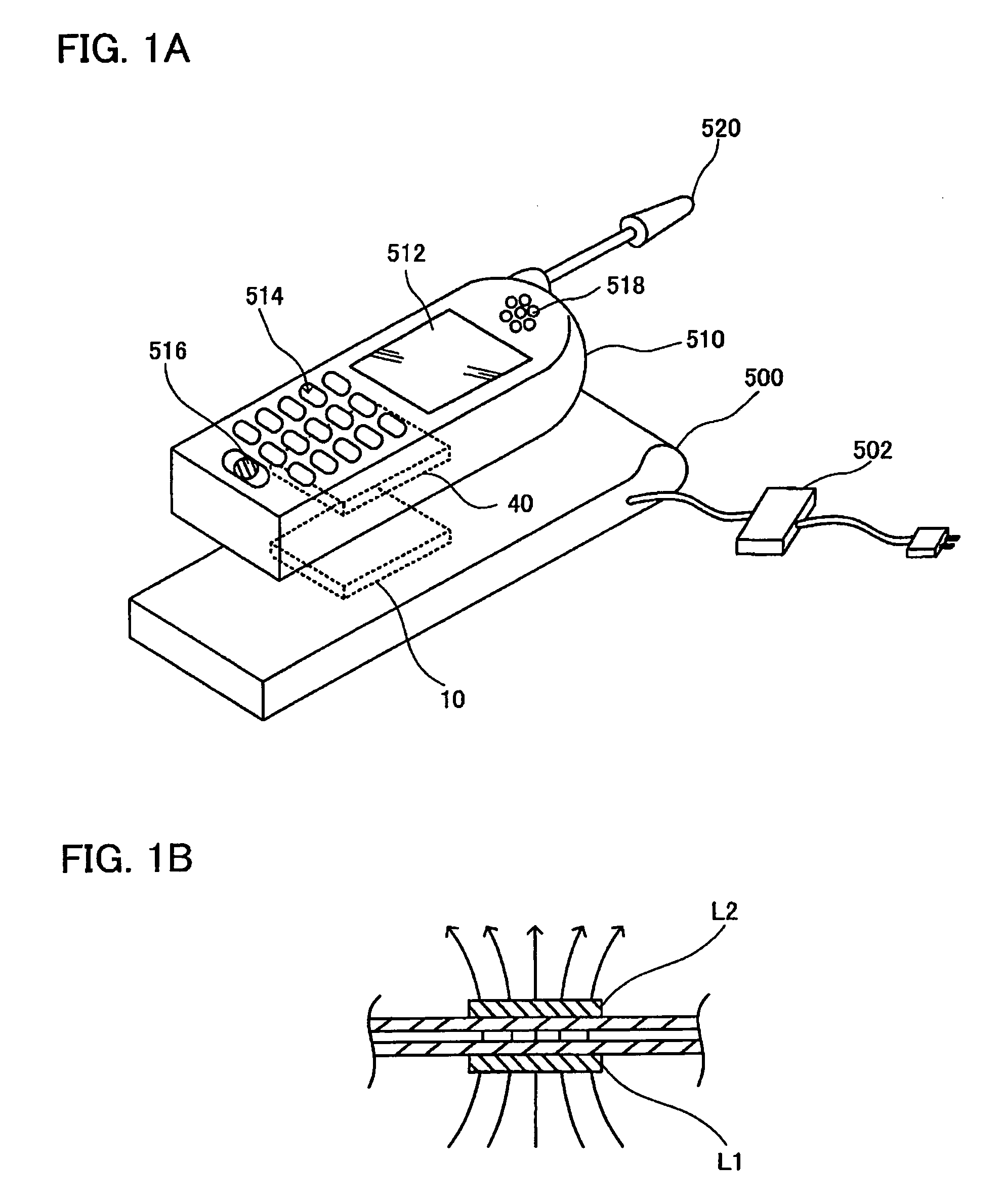
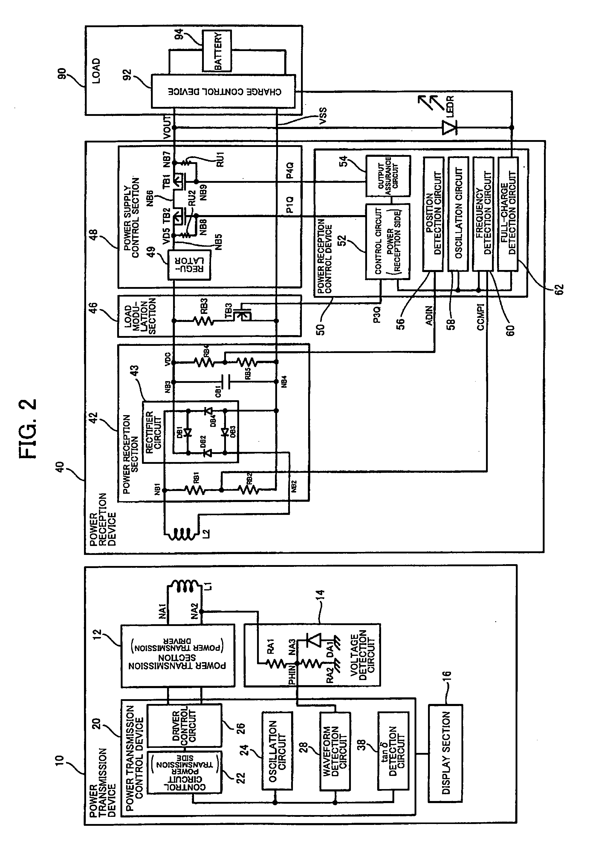
[0030]According to one embodiment of the invention, there is provided a power transmission device that includes a primary coil and electromagnetically couples the primary coil with a secondary coil of a power reception device to supply power to a load of the power reception device, the power transmission device comprising:

[0031]a first coil connection terminal and a second coil connection terminal respectively connected to ends of the primary coil;

[0032]a resonant capacitor that forms a series resonant circuit with the primary coil;

[0033]a first power transmission driver and a second power transmission driver that drive the primary coil from the ends of the primary coil through the first coil connection terminal and the second coil connection terminal; and

[0034]a control IC that outputs driver control signals to the first power transmission driver and the second power transmission driver,

[0035]the first coil connection terminal, the second coil connection terminal, the resonant capa...


PUM


Abstract

A control IC for first and second transmission drivers that drive a primary coil includes an output terminal connected to the first transmission driver on a first side, an output terminal connected to the second transmission driver on a second side, and an input terminal to which a waveform of a coil connection terminal is input through a waveform detection wiring pattern on a third side. The control IC is disposed in a center area of a board at a position shifted in a first direction with respect to a centerline. The coil connection terminal and a resonant capacitor are disposed in first and second row positions on the end of the board. The first transmission driver is disposed at a position shifted in the first direction with respect to the first side of the control IC. The second transmission driver is disposed at a position opposite to the second side of the control IC. The waveform detection wiring pattern extends from the third side of the control IC to the coil connection terminal through an area shifted in a second direction with respect to the centerline.

Description

[0001]Japanese Patent Application No. 2007-139282 filed on May 25, 2007, is hereby incorporated by reference in its entirety.BACKGROUND OF THE INVENTION[0002]The present invention relates to a power transmission device which performs non-contact power transmission, an electronic instrument, and the like.[0003]In recent years, non-contact power transmission (contactless power transmission) that utilizes electromagnetic induction to enable power transmission without metal-to-metal contact has attracted attention. As application examples of non-contact power transmission, charging a portable telephone, a household appliance (e.g., telephone handset), and the like has been proposed.[0004]JP-A-2006-60909 discloses non-contact power transmission. In JP-A-2006-60909, a series resonant circuit is formed using a resonant capacitor connected to the output of a power transmission driver and a primary coil so that power is supplied from a power transmission device (primary side) to a power rece...

Claims


Application Information

Patent Timeline
Patent Type & Authority Applications(United States)
IPC IPC(8): H02J5/00H02J7/00
CPCH02J7/025H02J7/00045H02J7/0044H02J50/12H02J50/60H02J50/90
Inventor ONISHI, KOTASOGABE, HARUHIKO
Owner SEIKO EPSON CORP
Why Eureka
Try Eureka