Inductance Element

a technology of inductance elements and components, applied in the direction of inductances, transformers/inductance details, coils, etc., can solve the problems of large amount of adhesive required, connection failure, deterioration of adhesive strength, etc., and achieve the effect of sufficient fixation strength

Active Publication Date: 2008-11-27
SUMIDA CORP
View PDF12 Cites 15 Cited by
  • Summary
  • Abstract
  • Description
  • Claims
  • Application Information

AI Technical Summary

Benefits of technology

[0026]With this structure, the side portion contacts the outer wall face of the ring-shaped member, the mounting portion is placed in a first side (a surface facing to the mounting substrate of the first core portion) and the terminal connecting portion is placed in a second side (a surface opposite to a surface facing to

Problems solved by technology

There has been a problem that an advanced downsizing can cause deterioration of adhesive strength since the adhesion area of the hoo

Method used


Image

  • Inductance Element
  • Inductance Element
  • Inductance Element

Examples


Embodiment Construction

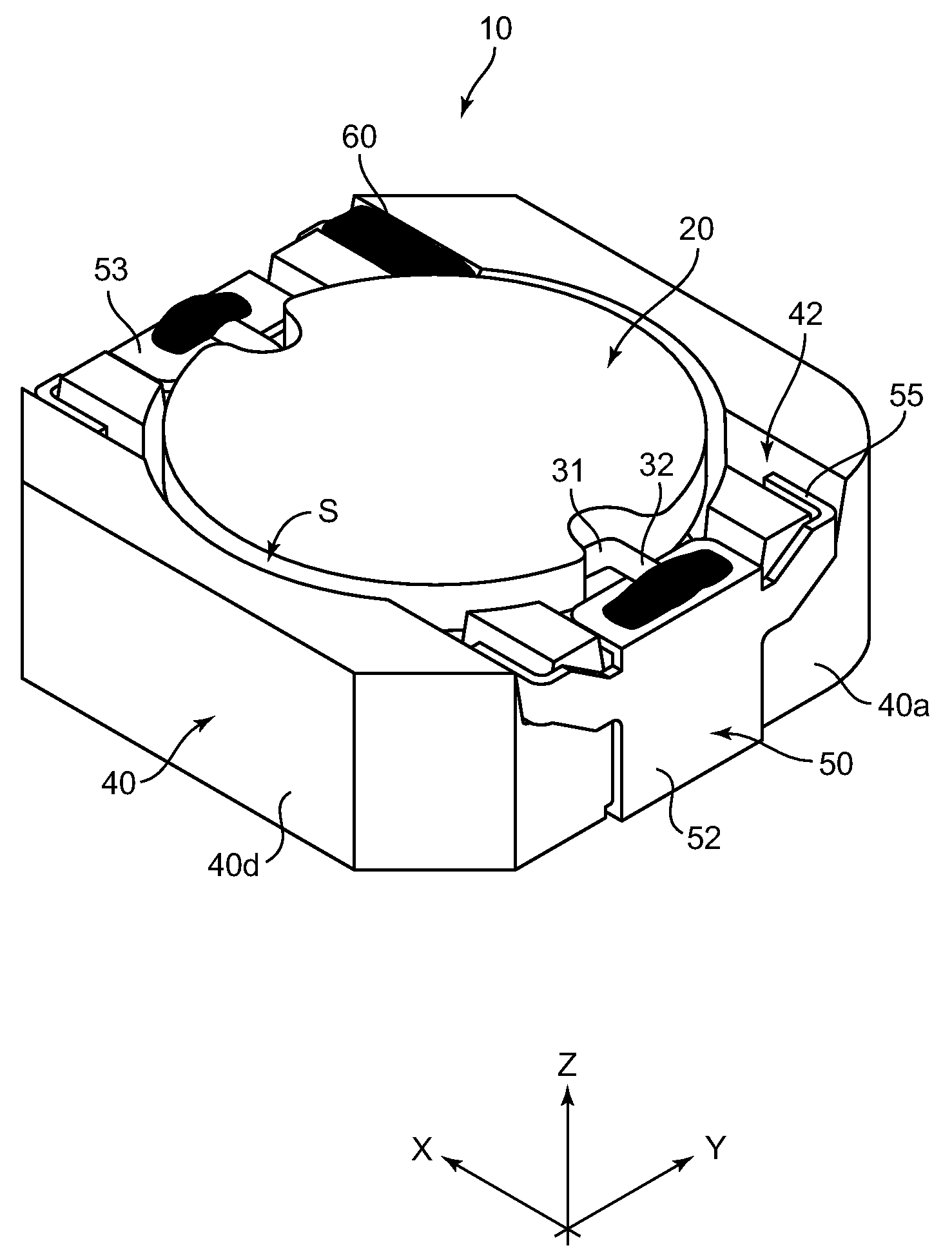
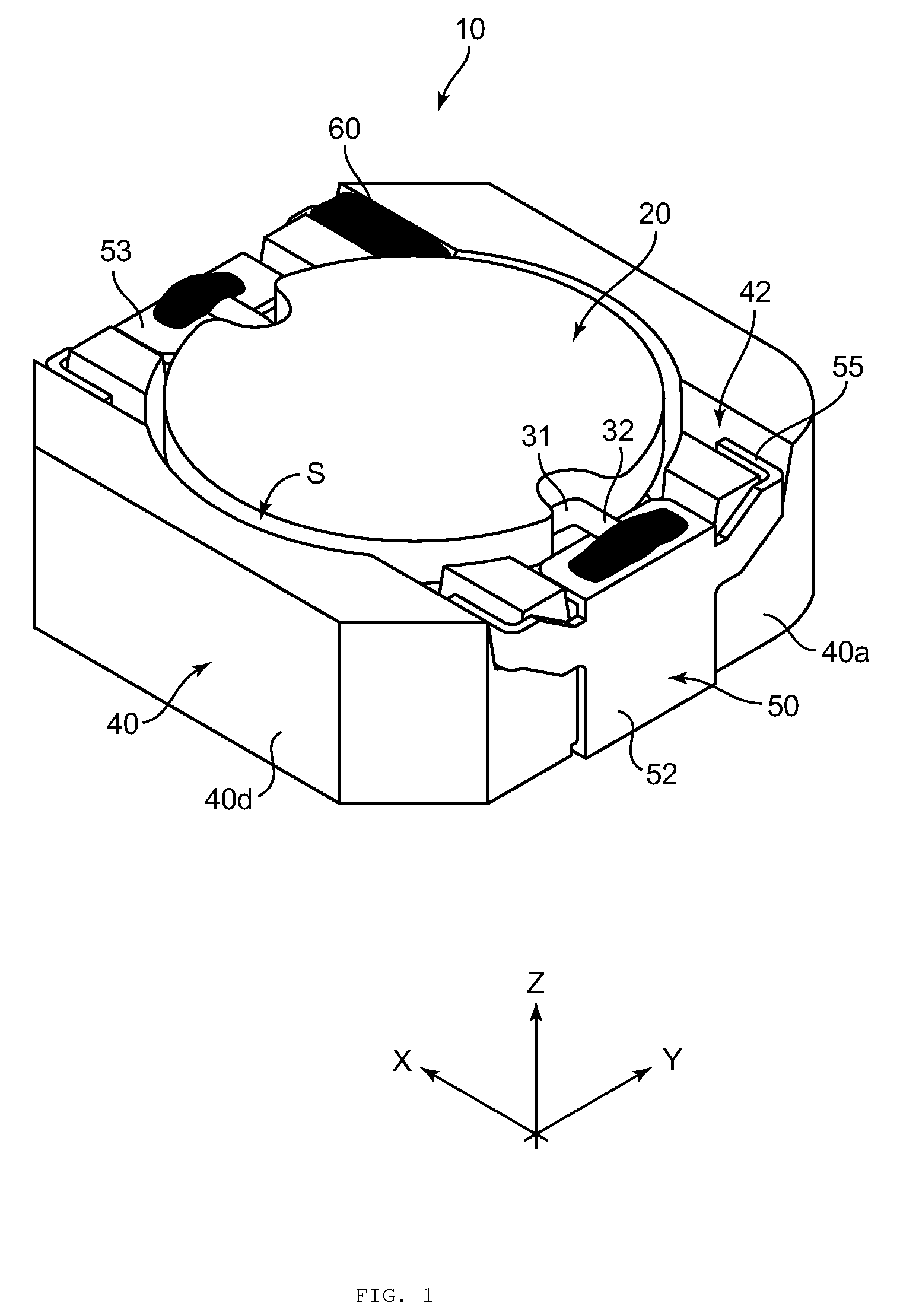
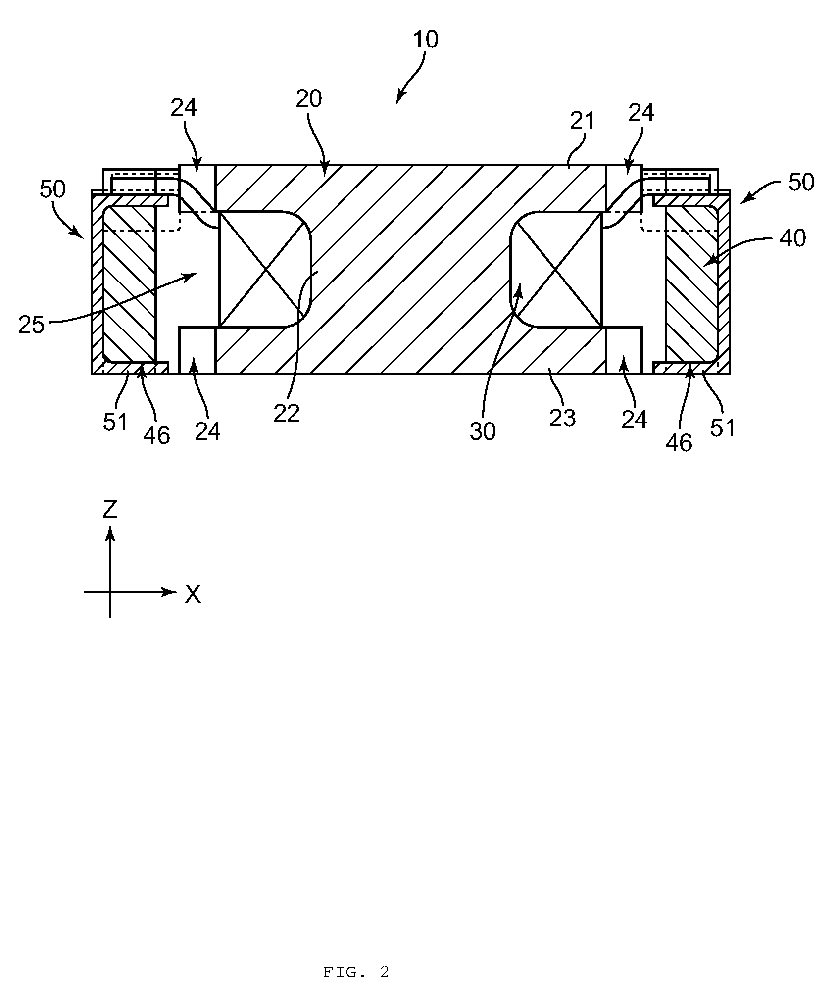
[0038]An inductance element 10 according to an embodiment of the present invention will be described with reference to FIGS. 1 to 11.

[0039]As shown in FIGS. 1 and 2, the inductance element 10 of the present embodiment includes a drum core 20, a coil 30, a ring-shaped member 40 and a hoop terminal 50. The drum core 20 has an upper flange portion 21, a column portion 22, a lower flange portion 23.

[0040]The drum core 20 is a disk-drum body having a center axis L shown in FIG. 3 and the upper flange portion 21, column portion 22 and lower flange portion 23 are formed in circular shapes in a plane view. The drum core 20 corresponds to a first core portion. Further, the drum core 20 is made of a magnetic material such as a nickel ferrite core, for example. Here, the magnetic material is not limited to the nickel ferrite core and a manganese ferrite core is also acceptable. Similarly, the material of the drum core 20 is not limited to the ferrite core, and the other magnetic materials such...


PUM


Abstract

An inductance element has a first core portion having a winding frame portion; a coil provided on the winding frame portion; a ring-shaped member having an insertion hole to dispose the first core portion therein; and a terminal member having an bonding arm to be fixed to the ring-shaped member via an adhesive member, and a mounting portion.

Description

CROSS-REFERENCE TO RELATED APPLICATIONS[0001]This application relates to and claims priority rights from Japanese Patent Application No. 2007-139491, filed on May 25, 2007, the entire disclosure of which is hereby incorporated by reference herein.BACKGROUND[0002]1. Technical Field[0003]The present invention relates to an inductance element used in an electronic equipment such as a cellular phone, a digital camera, a mobile device and a laptop personal computer.[0004]2. Related Art[0005]Some inductance elements include a drum-type core and some include a ring-type core. Among these types of inductance elements, there is an inductance element in which a hoop terminal is provided on an outer peripheral surface of a ring-type core. Such an inductance element is disclosed in Japanese Patent Application Laid-Open No. 2003-168616. According to the inductance element of Japanese Patent Application Laid-Open No. 2003-168616 (see paragraph 0036 and FIG. 3), a mounting portion, which is in a l...

Claims


Application Information

Patent Timeline
IPC IPC(8): H01F27/02
CPCH01F3/10H01F17/043H01F17/045H01F27/292
Inventor WATANABE, TSUTOMU
Owner SUMIDA CORP
Why Eureka
Try Eureka