Optical scanning unit and electro-photographic image forming apparatus including the same

a scanning unit and electro-photographic technology, applied in the direction of electrographic process equipment, printing, instruments, etc., can solve the problems of reducing the quality of printed images formed by the photosensitive body, focusing movement, and light radiated from the light source may not be accurately focused on the photosensitive body, so as to prevent the movement of the focus

Active Publication Date: 2008-11-27
HEWLETT PACKARD DEV CO LP
View PDF5 Cites 9 Cited by
  • Summary
  • Abstract
  • Description
  • Claims
  • Application Information

AI Technical Summary

Benefits of technology

[0006]To solve the above and / or other problems, aspects of the present invention provide an optical scanning unit, which can compensate for temperature changes and thereby prevent focus movement, and an electro-photographic image forming apparatus that employs the optical scanning unit.

Problems solved by technology

Refractive indexes of the above lenses vary according to temperature, and such variations may cause focus movement.
For example, the light radiated from the light source may not be accurately focused on the photosensitive body.
If focus movement occurs, the light may be improperly focused onto a photosensitive body, thereby reducing the quality of printed images formed by the photosensitive body.

Method used


Image

  • Optical scanning unit and electro-photographic image forming apparatus including the same
  • Optical scanning unit and electro-photographic image forming apparatus including the same
  • Optical scanning unit and electro-photographic image forming apparatus including the same

Examples


Embodiment Construction

[0022]Reference will now be made in detail to the present embodiments of the present invention, examples of which are illustrated in the accompanying drawings, wherein like reference numerals refer to the like elements throughout. The embodiments are described below in order to explain the present invention by referring to the figures.

[0023]Aspects of the present invention will now be described more fully with reference to the accompanying drawings in which exemplary embodiments of the invention are shown.

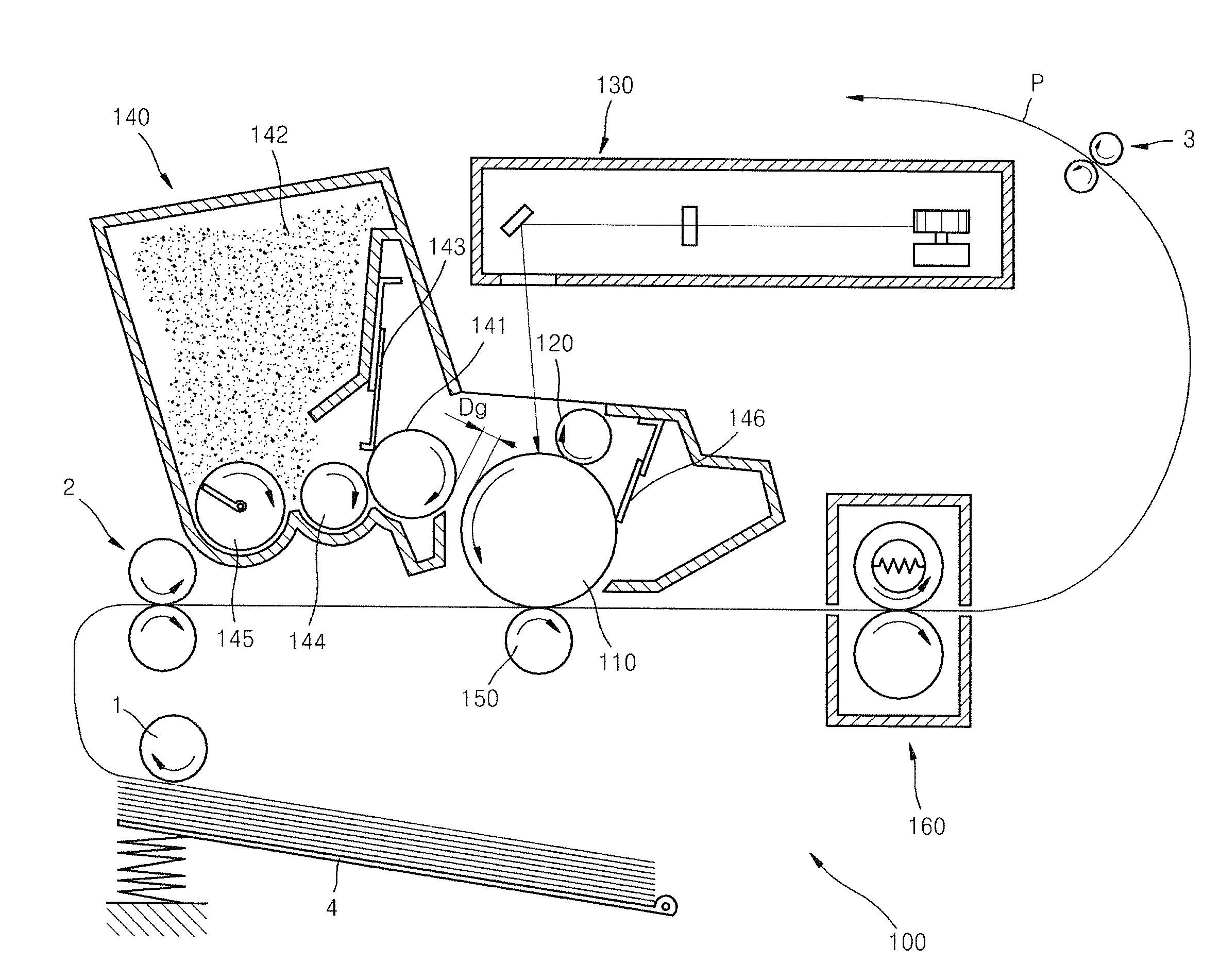
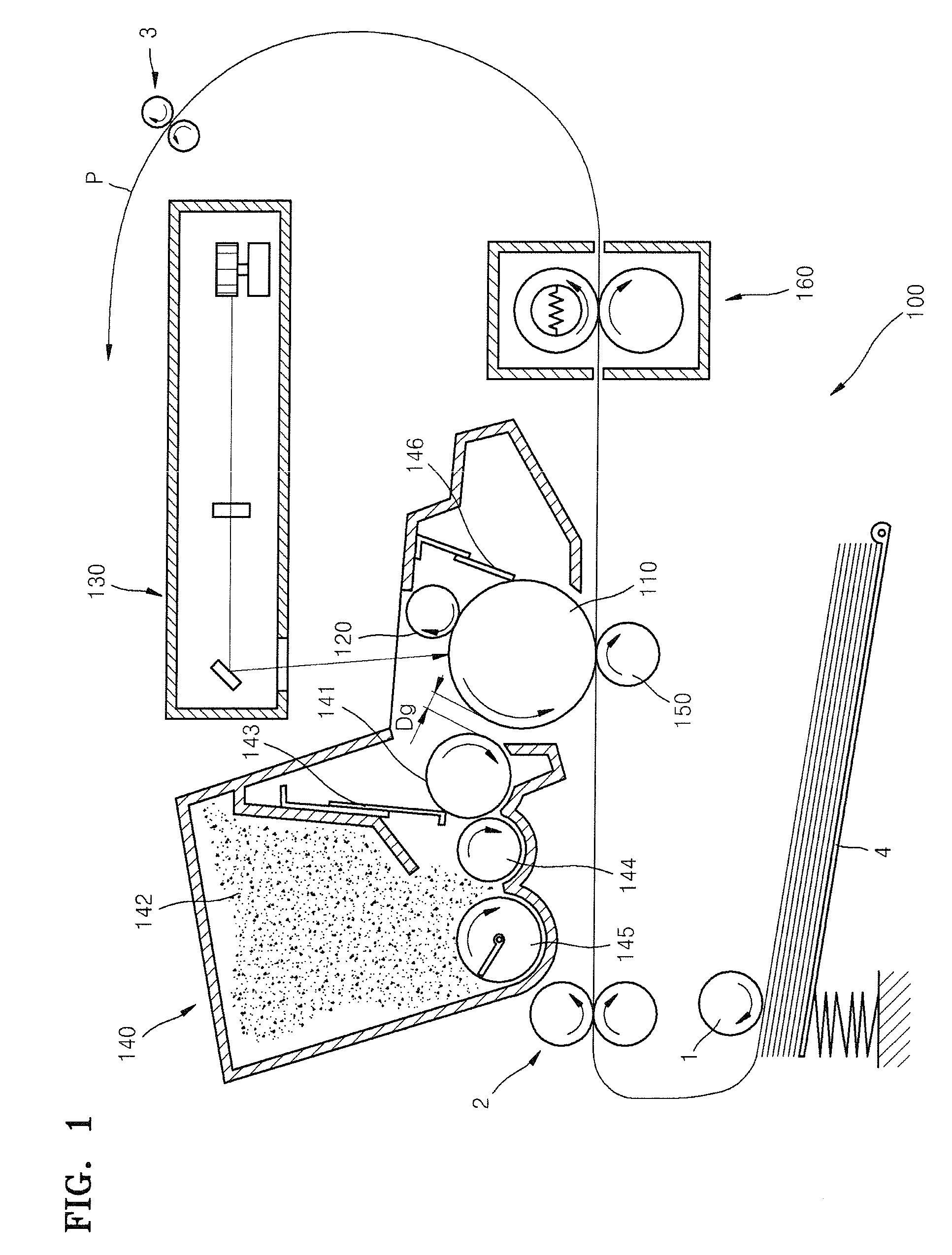
[0024]FIG. 1 is a schematic drawing showing the configuration of an electro-photographic image forming apparatus 100, according to an exemplary embodiment of the present invention. Referring to FIG. 1, the electro-photographic image forming apparatus 100 includes a photosensitive drum 110, a charge roller 120, an optical scanning unit 130, a developing unit 140, a transfer roller 150, and a fixing unit 160.

[0025]The photosensitive drum 110 is an example of a photosensitive body, an...


PUM


Abstract

An optical scanning unit that includes a first optical device that forms collimated light from light radiated from a light source, a second optical device that focuses the collimated light onto a deflector, and an imaging optical device that focuses light deflected by the deflector onto an exposure object. The optical scanning unit further includes a refraction unit and a diffraction unit, and the power of the refraction unit is φr, the power of the diffraction unit is φd, and the ratio φr/φd is such that 0.5<φr/φd<1.3.

Description

CROSS-REFERENCE TO RELATED APPLICATION[0001]This application claims the benefit of Korean Application No. 2007-50999, filed May 25, 2007, in the Korean Intellectual Property Office, the disclosure of which is incorporated herein by referenceBACKGROUND OF THE INVENTION[0002]1. Field of the Invention[0003]Aspects of the present invention relate to an optical scanning unit and an electro-photographic image forming apparatus that employs the same.[0004]2. Description of the Related Art[0005]An electro-photographic image forming apparatus includes an optical scanning unit that scans light modulated in response to image information, to a photosensitive body (exposure object), and deflects the light in a main scanning direction using a deflector, such as a polygon mirror. The optical scanning unit includes a collimating lens, a cylindrical lens, and an fθ lens, in order to focus light radiated from a light source, onto a photosensitive body. Refractive indexes of the above lenses vary acco...

Claims


Application Information

Patent Timeline
Patent Type & Authority Applications(United States)
IPC IPC(8): G03G21/00
CPCG02B5/1895G02B26/124G02B26/127G02B26/10G03G15/04
Inventor KU, JONG-WUK
Owner HEWLETT PACKARD DEV CO LP
Why Eureka
Try Eureka