Laryngoscope that indicates contact

a technology of laryngoscope and contact lens, which is applied in the field of laryngoscope, can solve the problems of inadvertent contact of laryngoscope blade with patient's teeth, damage or displacement of teeth, and inconvenient use of laryngoscope blades

Inactive Publication Date: 2008-11-27
COOPER JOHN D
View PDF4 Cites 22 Cited by
  • Summary
  • Abstract
  • Description
  • Claims
  • Application Information

AI Technical Summary

Problems solved by technology

However, conventional laryngoscope blades do not protect the patient's teeth during intubation.
That is, in the process of manipulating the laryngoscope blade, the laryngoscope blade can inadvertently come in contact with the patient's teeth.
The levering forces of the laryngoscope placed on the patient's teeth can cause damage to or displacement of the teeth.
Moreover, conventional laryngoscope blades cannot provide any warning of this impending dental damage.
Thus, while conventional laryngoscope devices may be suitable for providing intubation, they do not suitably protect the patient's teeth during the laryngeal intubation process.
For example, because many laryngoscope blades are made of metal or a high tensile strength plastic, inadvertent contact by the laryngoscope blade with the patient's teeth could cause damage or displacement of the teeth.

Method used


Image

  • Laryngoscope that indicates contact
  • Laryngoscope that indicates contact
  • Laryngoscope that indicates contact

Examples


Embodiment Construction

[0023]Reference will now be made in detail to an exemplary embodiments of the present invention, examples of which are illustrated in the accompanying drawings, wherein like reference numerals refer to like elements throughout. It is to be understood that the invention is not limited in its application to the details of construction and to the arrangements of the components set forth in the following description or illustrated in the drawings. The invention is capable of other embodiments and of being practiced and carried out in various ways. Also, it is to be understood that the phraseology and terminology employed herein are for the purpose of the description and should not be regarded as limiting.

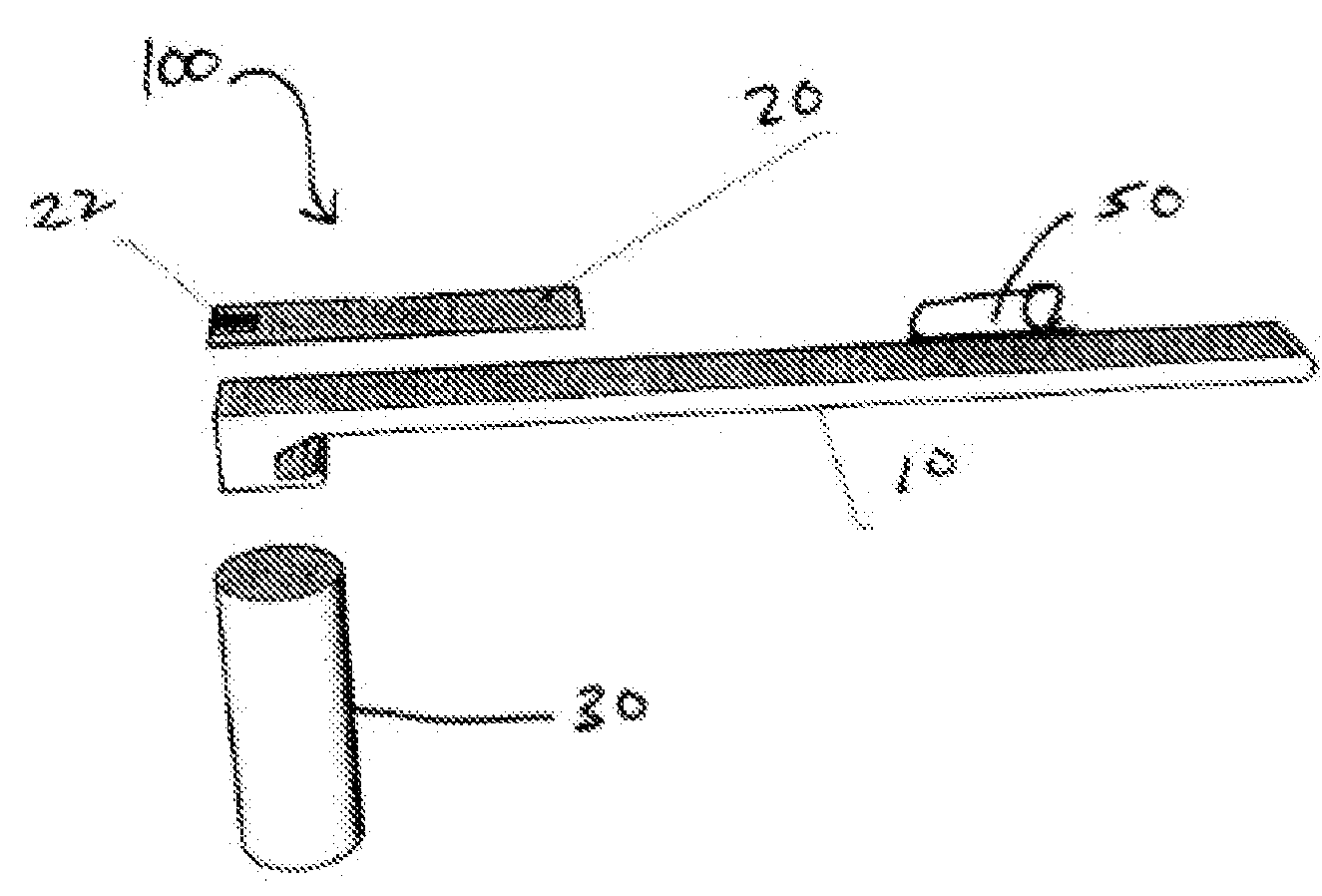
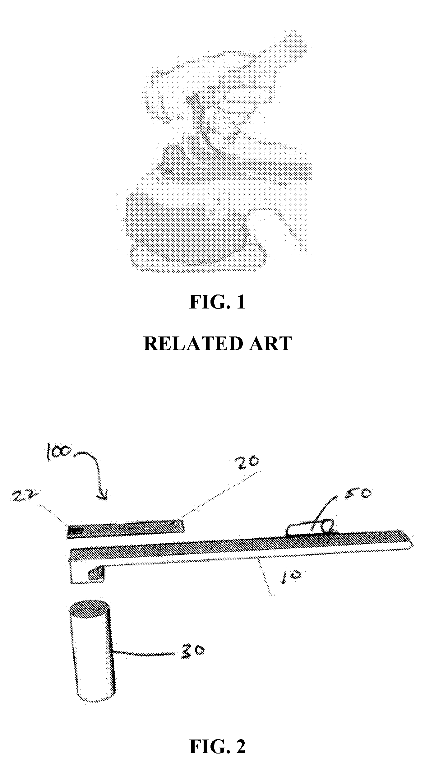
[0024]A first exemplary embodiment of the laryngoscope is shown in FIG. 2. The laryngoscope 100 generally includes a laryngoscope blade 10, a sensor body 20 attached to the laryngoscope blade 10, and a handle 30. The laryngoscope blade 20 is typically a rigid member made of metal or a h...


PUM


Abstract

A laryngoscope including a laryngoscope blade and a detector incorporated in or attached to the laryngoscope blade, the detector detecting contact. A method of using a laryngoscope including moving a patient's pharyngeal structure using a laryngoscope blade, wherein a detector is attached to the laryngoscope blade; contacting the patient's teeth with the detector; and indicating a contact between the detector and the teeth.

Description

[0001]This application claims priority from U.S. provisional application No. 60 / 940,161, which was filed on May 25, 2007, the entire contents of which are hereby incorporated by reference.BACKGROUND OF THE INVENTION[0002]1. Field of the Invention[0003]Devices and methods and consistent with the present invention relate to a laryngoscope and the use thereof and more specifically to a laryngoscope which indicates dental contact for the protect of teeth during the laryngeal intubation process and the use thereof.[0004]2. Description of the Related Art[0005]Intubation generally refers to a process by which a tube is placed into an external or internal orifice of the body. However, intubation most often refers to the laryngeal intubation process, in which a tube is placed in a patient's trachea. A laryngoscope with a laryngoscope blade has been used to assist with laryngeal intubation for many years. Typically, an end of a laryngoscope blade is inserted into the patient's open mouth, and...

Claims


Application Information

Patent Timeline
Patent Type & Authority Applications(United States)
IPC IPC(8): A61B1/267
CPCA61B1/267A61B1/00055
Inventor COOPER, JOHN D.
Owner COOPER JOHN D
Why Eureka
Try Eureka