Joining Panel

a joint panel and panel technology, applied in the field of covering panels, to achieve the effect of simple and fast operation, easy and economical storage over longer time intervals, and simple structur

Inactive Publication Date: 2008-12-04
KAINDL FLOORING GMBH
View PDF10 Cites 57 Cited by
  • Summary
  • Abstract
  • Description
  • Claims
  • Application Information

AI Technical Summary

Benefits of technology

[0005]The priority object of the invention is to be able to manufacture panels of the above-mentioned type as easily and economically as possible, furthermore to enable their storage over longer time intervals without adverse effects and in a space-saving way, and finally to make installation, and optionally dismantling, as panel conserving, fast and simple as possible. Another object is to prepare a stable, durable and solid surface from the interconnected panels; during installation, however, an alignment of the panels should be possible over a certain time interval. The groove and the tongue should be able to be produced in a stable and simple way, and should well be able to be latched; the bead or web of an adhesive and / or of a plastic material should be able to be applied in a simple and durable way.

Problems solved by technology

This sealing material or this adhesive, however, do not act per se as an interlocking element and do not contribute to a mechanical force-locking or positive lock of two panel elements to be interconnected.

Method used


Image

  • Joining Panel
  • Joining Panel

Examples


Embodiment Construction

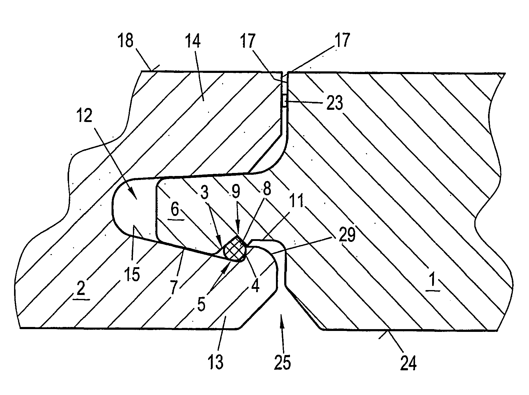
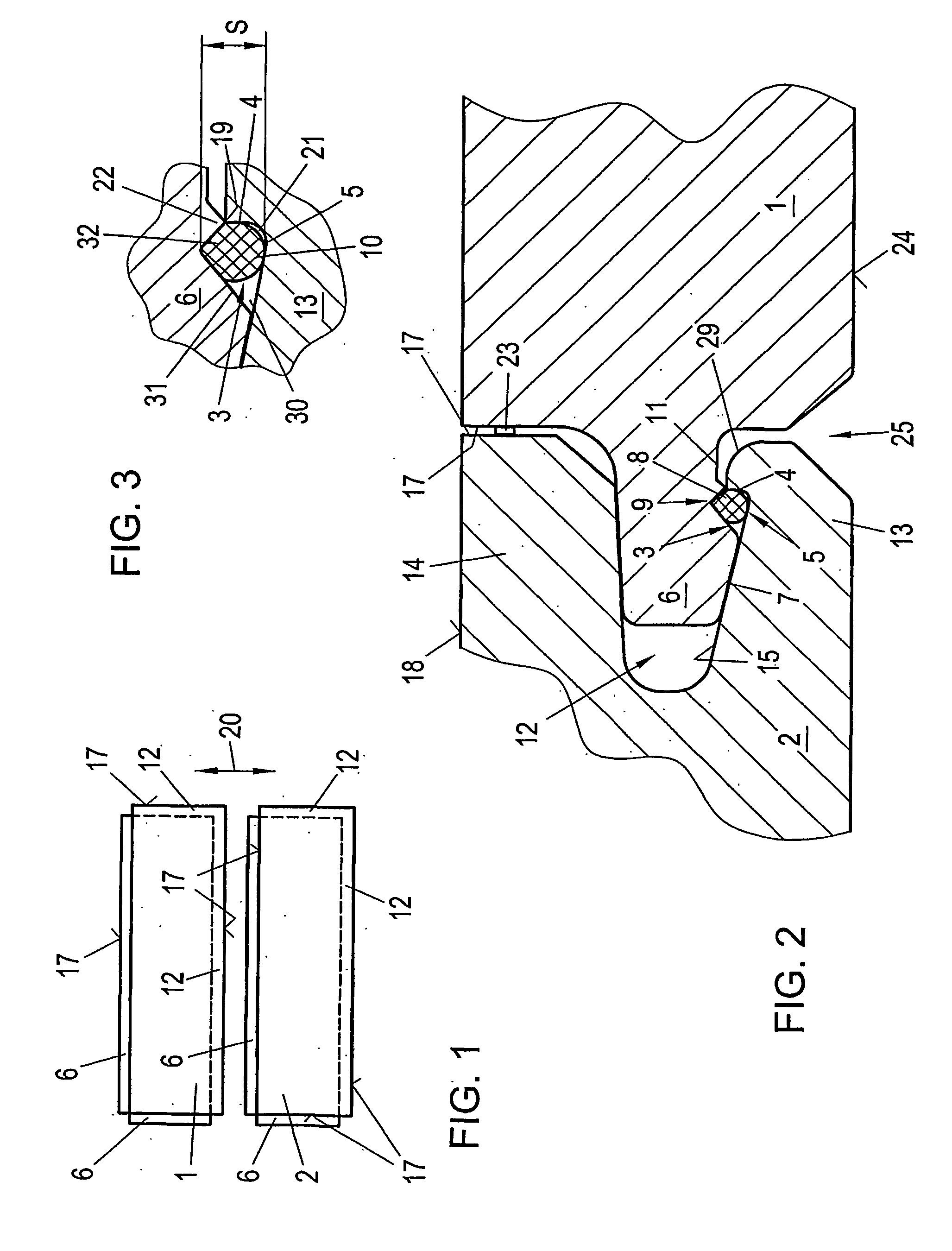
[0038]FIG. 1 illustrates schematically two covering panels 1, 2 which are to be pushed to one another in the direction of arrow 20 and should be joined to one another. This joining by displacement, as the last joining step, can and should be carried out only in the plane spanned by the two panels 1, 2. On their longitudinal sides and / or their narrow side, the two panels each have a tongue 6, which projects from the front surface 17, and a groove 12 formed in the front surface 17 at the opposite longitudinal side and / or narrow side. The same conditions may prevail on the front surfaces 17 of the narrow sides; each of the panels 1, 2 may have a groove 12 and a tongue 6 on the front surface 17 of these narrow sides.

[0039]The shapes of the tongue and the groove are matched to one another in order to ensure a good connection between the groove and the tongue. This shape allows insertion of the tongue 6 into the groove 12, when the panels 1, 2 are aligned in the plane of the panels. It is...


PUM


Abstract

Covering panel(s) for floors have a groove (12) along at least one edge and have a tongue (6) along another edge (17). Panels (1, 2) to be joined to one another can be joined by inserting the tongue (6) into the groove (12). A bead (8) made of an adhesive and / or plastic is placed on or affixed to at least one tongue surface (7). According to the invention, a recess (3) is formed in the tongue surface (7) and serves to accommodate the bead (8), and a detent recess (5), which is delimited by a detent surface (4), is formed in the inside wall surface (15) of the groove, this surface facing the tongue surface (7). When the tongue (6) is inserted into the groove (12), the bead (8) projects into the detent recess (5) whereby enabling the bead (8) and the detent surface (4) to latch.

Description

CROSS-REFERENCES TO RELATED APPLICATIONS[0001]This application claims the priority of Austrian Patent Application A 511 / 2004 filed Mar. 23, 2004, and is a U.S. National Phase application of PCT / AT 2005 / 000054 filed Feb. 21, 2005, both of which disclosures are incorporated herein by reference.BACKGROUND OF THE INVENTION[0002]The invention concerns a covering panel for floors, walls or ceilings or similar purposes of use in accordance with the introductory clause of claim 1.[0003]Such panels have grooves and tongues on their lateral surfaces in order to be able to install these panels in a formation. In order to achieve a formation as stable as possible, it can also be provided that the panels be cemented to one another.[0004]From the prior art, interlocking elements have become known, which are cooperating or which fit to one another, sealing material being applied for sealing the interlocking regions or an adhesive is introduced for forming a connection of the interlocking elements....

Claims


Application Information

Patent Timeline
Patent Type & Authority Applications(United States)
IPC IPC(8): E04C2/00F16B5/00E04B9/04E04F13/10E04F15/02E04F15/04F16B11/00
CPCE04B9/0435E04F13/10E04F15/02Y10T403/642E04F2201/0115F16B5/0012F16B11/006E04F15/04E04F2201/07F16B2200/503
Inventor KNAUSEDER, FRANZ
Owner KAINDL FLOORING GMBH
Why Eureka
Try Eureka