Ultrasound prediction of workpiece deformation

a workpiece and ultrasonic technology, applied in the direction of instruments, heat measurement, specific gravity measurement, etc., can solve the problems of increasing the number of machining operations, requiring significant additional costs, and unable to deduce the most suitable procedure from the experience gained in machining, etc., to achieve the effect of simple implementation, effective and effectiv

Active Publication Date: 2008-12-04
SN DETUDE & DE CONSTR DE MOTEURS DAVIATION S N E C M A
View PDF11 Cites 8 Cited by
  • Summary
  • Abstract
  • Description
  • Claims
  • Application Information

AI Technical Summary

Benefits of technology

[0004]It is a particular object of the invention to provide a method for estimating the deformation o

Problems solved by technology

However, increasing the number of machining operations entails a significant additional cost because of the relatively lengthy time needed for each machining operation.
Exp

Method used


Image

  • Ultrasound prediction of workpiece deformation
  • Ultrasound prediction of workpiece deformation

Examples


Embodiment Construction

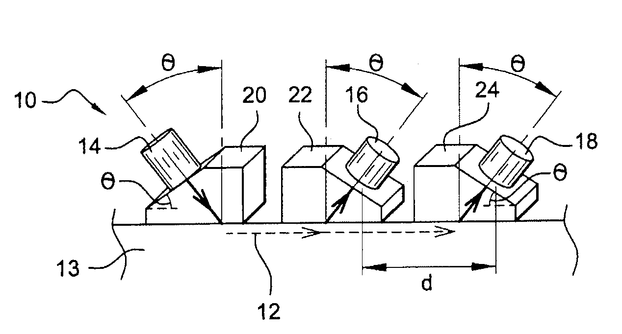
[0032]Reference is made first of all to FIG. 1 which depicts a device 10 for measuring the velocity of an ultrasound subsurface longitudinal wave 12 (represented as dotted arrows) propagating through a workpiece 13. The device comprises an emitting transducer 14 and two receiving transducers 16, 18 positioned on coupling pieces 20, 22, 24 in such a way that their ultrasound axes are perpendicular to an inclined plane of their coupling pieces. The receiving transducers are separated by a known distance d. The inclined plane of the coupling piece 20 of the emitting transducer 14 makes an angle θ with the surface of the workpiece and this plane is directed in the counterclockwise direction. The inclined planes of the coupling pieces 22, 24 of the receiving transducers 16, 18 make the same angle θ with the surface of the workpiece and are directed in the clockwise direction. Thus, the ultrasound axis of each of the transducers also makes an angle θ with the surface of the workpiece. A c...


PUM


Abstract

Method of predicting the deformation of a workpiece (13) prior to machining that causes the workpiece to deform through release of residual stresses, which method consists in emitting a beam of ultrasound waves onto the surface of the workpiece (13) in such a way that a longitudinal wave (12) is propagated substantially parallel to and under the surface of the workpiece (13), then in measuring the propagation velocity of the subsurface longitudinal wave in a first region (A) sensitive to residual stresses and in a second region (B) somewhat insensitive to residual stresses, then in calculating the difference in the measured velocities and from this deducing the deformation that will result from machining the first region of the workpiece (13).

Description

BACKGROUND OF THE INVENTION [0001]The present invention relates to a method of predicting the deformation of a workpiece that is to be subjected to a machining operation and, in particular, relates to an application of this method to a high-pressure compressor disk in a turbomachine.[0002]The production of parts such as compressor disks usually entails several machining operations. Now, during machining, the workpiece may become deformed as a result of residual stresses present in the workpiece being released. When the deformation exceeds a certain value, the tolerances in terms of thickness, flatness and parallelism for example are no longer met and thus cause the machined workpiece to be scrapped, leading to significant financial losses.DESCRIPTION OF THE PRIOR ART [0003]In order to reduce the impact of the residual stresses during the machining operations, it is possible to carry out a larger number of machining operations in order to be able to limit the deformation. However, in...

Claims


Application Information

Patent Timeline
IPC IPC(8): G01N29/07
CPCG01N29/07G01N29/30G01N29/4436G01N2291/011G01N2291/02854G01N2291/0425G01N2291/057G01N2291/103G01N2291/2693
Inventor CHATELLIER, JEAN-YVES FRANCOIS ROGERLE LETTY, ERIC CHARLES, LOUIS
Owner SN DETUDE & DE CONSTR DE MOTEURS DAVIATION S N E C M A
Why Eureka
Try Eureka