Filter for Diesel Fuel with Heater

a technology for filtering and diesel fuel, applied in the direction of filtration separation, combustion-air/fuel-air treatment, separation process, etc., can solve the problem of relative high energy expense and achieve the effect of reducing energy expens

Inactive Publication Date: 2008-12-04
UFI FILTERS SPA
View PDF2 Cites 23 Cited by
  • Summary
  • Abstract
  • Description
  • Claims
  • Application Information

AI Technical Summary

Benefits of technology

[0010]There is therefore a real need to have available a filter for diesel fuel with heater which is capable of melting the possible solid paraffins present in the fuel itself, before they reach the filtering separator, with a lower energy expense than that required by the PTC resistors of the prior art, so as to correctly operate also with the voltages normally u

Problems solved by technology

As is known, the solidification of the paraffin substances in diesel fuel often causes problems at the starting of the automobiles fed with said fuel, since the solid paraffins thus formed depos

Method used


Image

  • Filter for Diesel Fuel with Heater
  • Filter for Diesel Fuel with Heater
  • Filter for Diesel Fuel with Heater

Examples


first embodiment

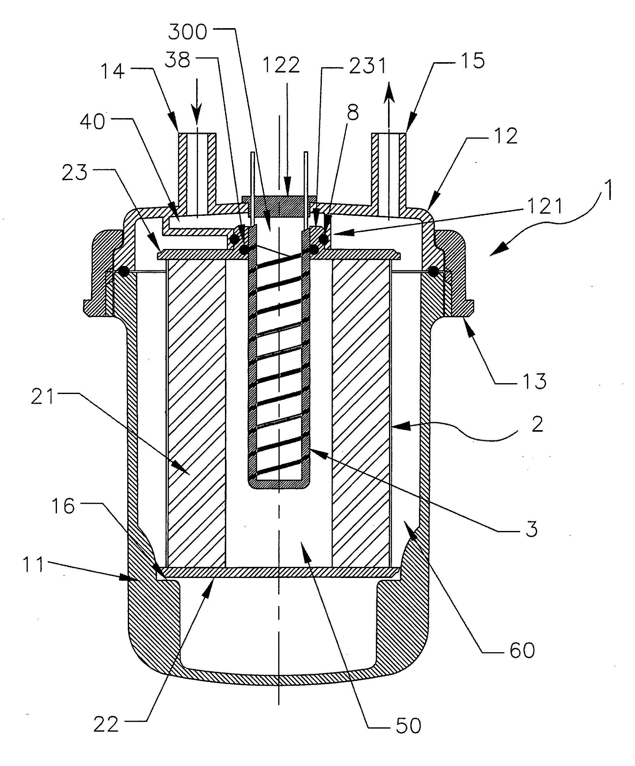
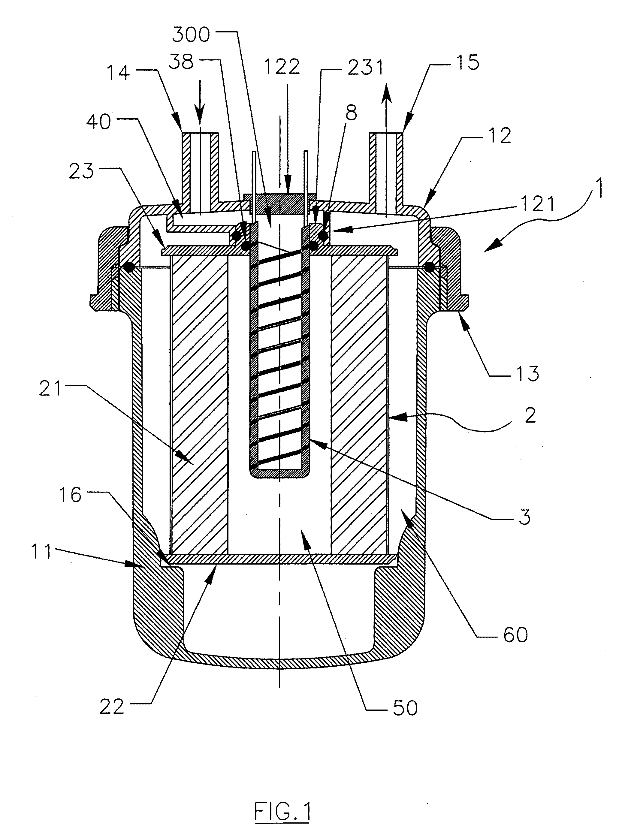
[0020]With reference to FIG. 1, where the present invention is illustrated, a filter for diesel fuel is indicated in its entirety with 1.

[0021]In brief, the filter 1 comprises a tank 11, an upper cover 12 seal-coupled on the tank 11 itself by means of a ring nut 13 or seam, an input conduit 14 of the fuel to be filtered, and an output conduit 15 of the filtered fuel.

[0022]At its interior, the tank 11 houses a filtering cartridge 2 which, associated with the cover 12, is adapted to subdivide the inner volume into two distinct chambers 50 and 60, of which the first 50 is in fluid communication with the input conduit 14 of the fuel to be filtered and the second 60 with the output conduit 15 of the filtered fuel.

[0023]The filtering cartridge 2 comprises a filtering separator 21 of tubular form, of known type, sustained between a lower plate 22 and an upper plate 23 to which it is firmly joined by means of normal fixing means such as glue or welding.

[0024]Essentially, the chamber 50 of t...

second embodiment

[0035]In FIGS. 4 and 5, the filter 1 is illustrated, wherein for the sake of simplicity the elements in common with the preceding embodiment are indicated with the same numeric references and are not newly described.

[0036]In particular, this second embodiment illustrates a filter 1′ comprising a heater, indicated with 3′, entirely analogous to that described above, which is however open on both opposite ends, i.e. is shaped as a cylinder.

[0037]The sintered heater 3′ is attached to a removable support 4 which may be associated to the filter 1 by means of rapid fixing means. Therefore, unlike the first embodiment wherein the heater 3 is definitively fixed to the upper plate 23 of the cartridge 2 through the O-ring 38, in this second embodiment it may be independently substituted from the cartridge 2 itself.

[0038]In the example of FIG. 4, the heater 3′, situated inside the chamber 50, has a cylindrical shape open at the two opposite ends; one end is fixed to the support 4 and the other...


PUM

PropertyMeasurementUnit
Lengthaaaaaaaaaa
Lengthaaaaaaaaaa
Electrical conductivityaaaaaaaaaa

Abstract

A filter (1) for diesel fuel comprising a tank (11), a filtering cartridge (2) which subdivides the inner volume of the tank (11) into two distinct chambers (50, 60), to which an input conduit (14) of the fuel to be filtered and an output conduit (15) of the filtered fuel are respectively connected, a heater (3), fed by means of electric current and adapted to melt the possible solid paraffins present in the fuel before they reach the filtering separator (21) of the cartridge (2), where said heater (3) has a porous surface (33, 34, 35) adapted to be crossed by the liquid component of the diesel fuel coming from the input conduit (14) and to hold the solid phase component, which forms at temperatures below the paraffination temperature, said porous surface (33, 34, 35) being adapted to be heated in order to liquefy said held solid component, so that it may cross said porous surface (33, 34, 35) in liquid form and reach the chamber (50) of the fuel to be filtered.

Description

TECHNICAL FIELD[0001]The present invention refers to a filter for diesel fuel in accordance with the preamble of claim 1.[0002]More in particular, the present invention refers to a filter for diesel fuel adapted to melt possibly formed paraffins before they reach the filtering separator.BACKGROUND ART[0003]As is known, the solidification of the paraffin substances in diesel fuel often causes problems at the starting of the automobiles fed with said fuel, since the solid paraffins thus formed deposit on the surface of the filtering separator, blocking the diesel fuel from passing through it.[0004]This occurs when the diesel fuel reaches a temperature below that at which paraffins begin to form.[0005]Hence, it is now common practice to install an electrical resistance heater, which begins to function when the fuel temperature is below the paraffination value, warming the diesel fuel in order to melt the solid paraffins, thereby permitting the subsequent filtering without obstruction.[...

Claims


Application Information

Patent Timeline
IPC IPC(8): B01D35/18
CPCB01D35/18F02M31/125F02M37/223Y02T10/126F02M37/30Y02T10/12
Inventor GIRONDI, GIORGIO
Owner UFI FILTERS SPA
Why Eureka
Try Eureka