B-shaped beam with radiused face but recessed center

a b-section beam and radiused face technology, applied in the field of b-section reinforcement beams, can solve the problems of high clearance requirements for the back of the beam, the tendency of the standard b-section beam to buckle during an impact, and the need for longer strokes for the bumper system

Inactive Publication Date: 2008-12-04
SHAPE CORP
View PDF4 Cites 16 Cited by
  • Summary
  • Abstract
  • Description
  • Claims
  • Application Information

AI Technical Summary

Problems solved by technology

However, it has been discovered that a “standard B-section beam” has a tendency to prematurely buckle during an impact, due in part to high stress concentration in the tight radius areas and due in part to buckle-type failure occurring in th

Method used


Image

  • B-shaped beam with radiused face but recessed center
  • B-shaped beam with radiused face but recessed center
  • B-shaped beam with radiused face but recessed center

Examples


Embodiment Construction

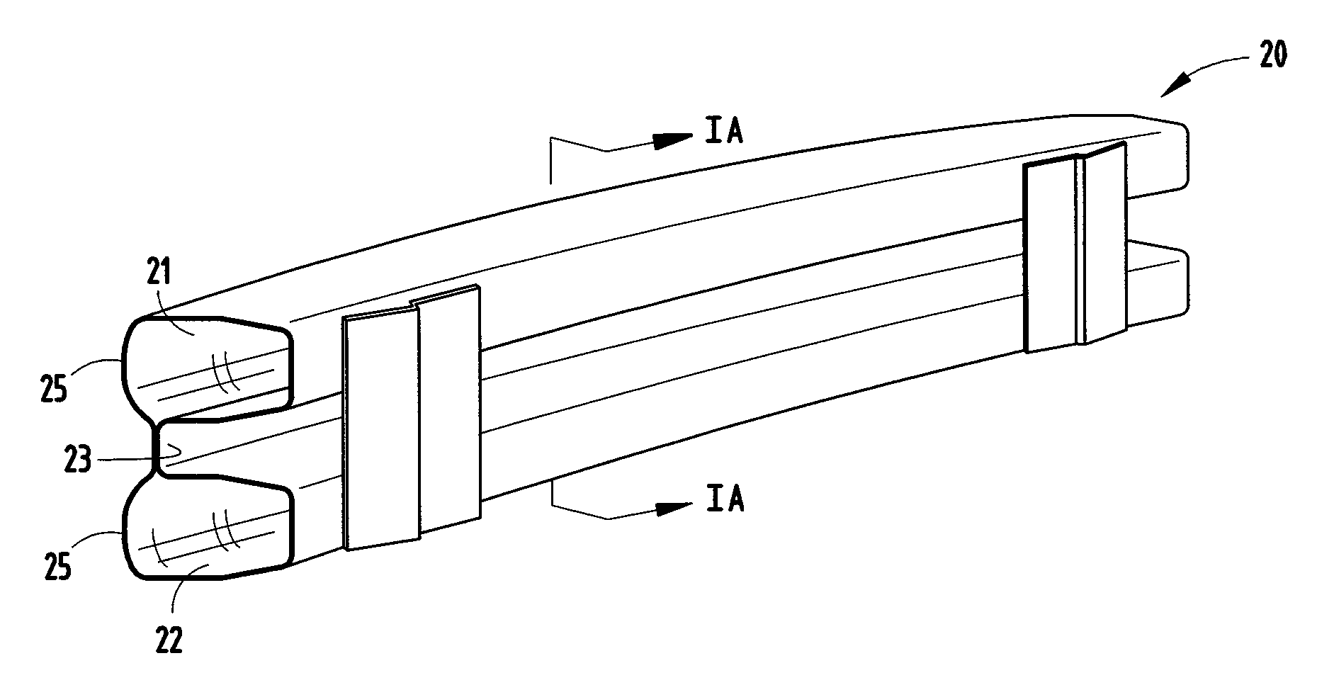
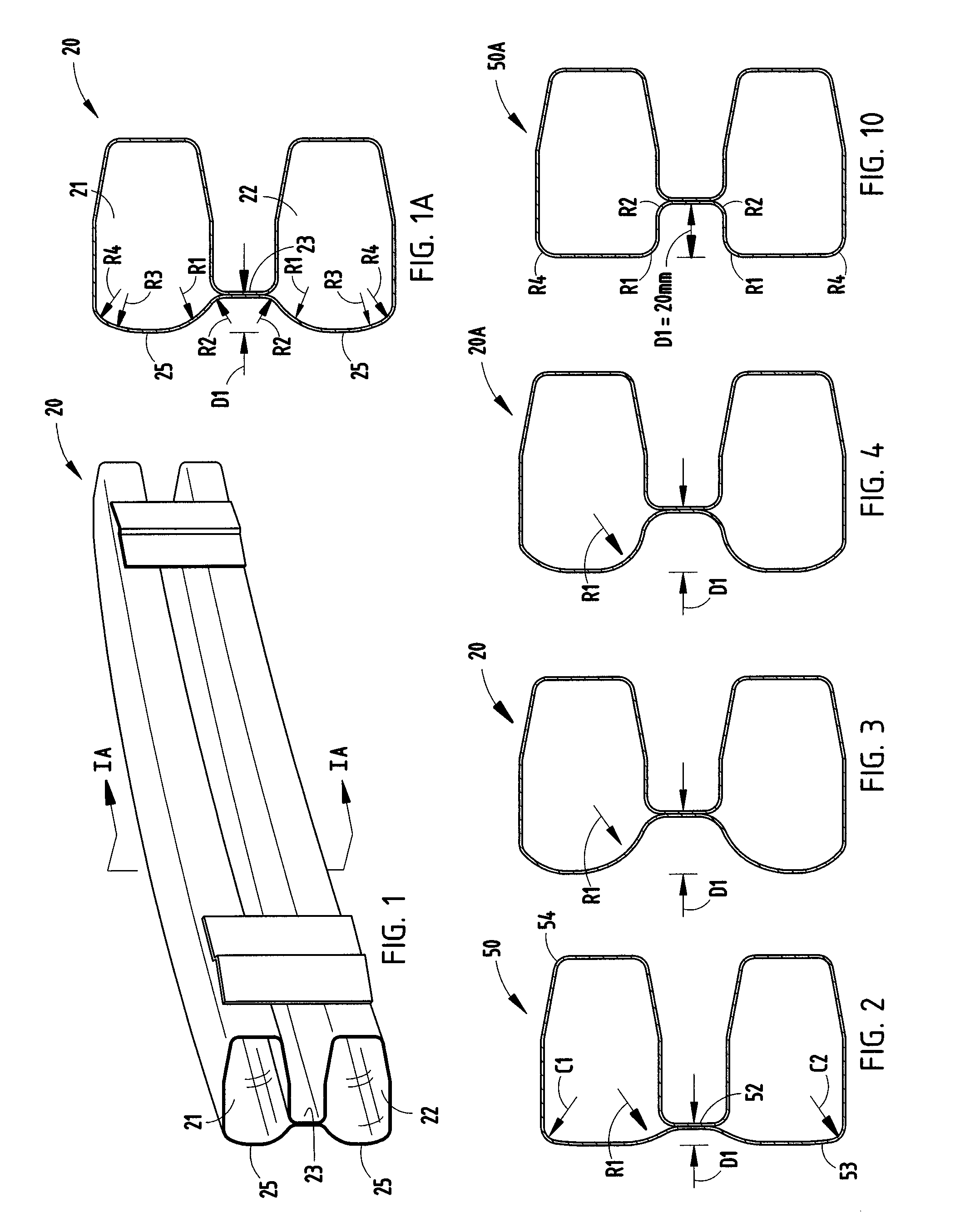
[0021]A B-shaped reinforcement beam 20 (FIGS. 1 and 1A) embodying the present invention has a face (i.e., front surface) with a particular non-linear radiused shape forming a front of each of the top and bottom tubes 21 and 22 in the beam, and a particular front depth of its center web 23. In the illustrated beam 20 (FIG. 1), the top and bottom portions are mirror images of each other top-to-bottom about a horizontal plane through the center web, such that the top and bottom tubes each include a sequence of radii R2, R1, R3, R4 defined in the face (starting from the channel out), and a depth dimension D1 defined by the center web 23 to highest point of the front wall, as discussed below.

[0022]More specifically, the illustrated B-shaped beam 20 is roll formed from a single sheet into a B shaped cross section, and then welded along the center web 23 to permanently define the top tube 21 and the bottom tube 22, the tubes 21, 22 being connected by the center web 23. When mounted to a ve...


PUM

PropertyMeasurementUnit
Lengthaaaaaaaaaa
Lengthaaaaaaaaaa
Fractionaaaaaaaaaa

Abstract

A B-shaped tubular reinforcement beam for vehicle bumper systems has a constant B section and longitudinal sweep. The tubular beam has a vertical cross section defining at least first and second tubes connected by a center web, and a front wall that extends across the tubes and the center web to define a channel. The channel has a depth dimension (D1) to the center web of about 15-30 mm, and preferably about 20 mm depth. The first and second tubes on their channel-side portion each include a section of wall defining a radius (R1) that is between about 15-30 mm, and preferably 25 mm.

Description

CROSS REFERENCE TO RELATED APPLICATION[0001]This claims benefit of a provisional application under 35 U.S.C. § 119(e), Ser. No. 60 / 941,129, filed May 31, 2007, entitled B-SHAPED BEAM WITH RADIUSED FACE BUT RECESSED CENTER.BACKGROUND[0002]The present invention relates to vehicle bumper systems, and more specifically relates to B-shaped reinforcement beams with a face wall having a particular radiused shape over its tubular sections and a recess in the center web between the tubular sections.[0003]It is known to manufacture B-shaped reinforcement beams for use in vehicle bumper systems. For example, see Sturrus U.S. Pat. No. 5,395,036, issued Mar. 7, 1995. However, “standard” B-section beams (historically) have a relatively flat front wall (often called its “face”) with tightly radiused corners at their upper and lower edges. The “standard” B-section beams (as exemplified by Sturrus '036) further include a relatively flat center web positioned at a location vertically aligned with upp...

Claims


Application Information

Patent Timeline
IPC IPC(8): B60R19/03
CPCB60R19/18Y10T29/49622B60R2019/1826
Inventor AGRAHARI, SHAILESH K.
Owner SHAPE CORP
Why Eureka
Try Eureka