
Photovoltaic panel support base rotating simultaneously around a horizontal and a vertical axis

a photovoltaic panel and support base technology, applied in the direction of photovoltaics, heat collector mounting/support, moving/orienting solar heat collectors, etc., can solve the problems of reducing the performance of photovoltaic panels, reducing design and manufacturing costs, and no dynamic stressing of fixed bases

Inactive Publication Date: 2011-06-02
DRITSAS VASILEIOS
View PDF2 Cites 34 Cited by
  • Summary
  • Abstract
  • Description
  • Claims
  • Application Information

AI Technical Summary

Benefits of technology

[0013]Furthermore, a main advantage of the present invention is that a rotation drive mechanism (Slew Drive) is used for the photovoltaic panels movement, by which it is possible for the photovoltaic panels to mechanically achieve a 180° movement and as position point 0 is considered to be the position point which is vertical with regard to the ground. In this way the photovoltaic panels, which are in accordance with the present invention, reach even the 97% of the maximum theoretical yield, as they are in contact with the solar rays for larger period of time.

Problems solved by technology

Furthermore, no dynamic stressing is created to fixed bases, caused by any moveable parts and movements, but only static stressing due to inertia loading or constant wind fall.
The main disadvantage of the fixed support bases is the reduced performance of the photovoltaic panels as only at the solar midday and only at summer there is maximum incident radiation.
The main disadvantage of the movable support bases is that there is an increased design and manufacture cost, an additional cost for purchasing ready made parts and products such as motor drive mechanisms, reduction gears, ball or not rotation bearings etc., as well as electrical and electronic equipment for the correct driving, the telecontrol and the remote control of the above drive mechanisms.
Due to all the above there is an uneven and asymmetric stressing of the cooperating gear wheels of movement transmission around the first or the second rotation axis, the changing stressing of the electric motors and the development of vibrations and oscillations at the support frame of the photovoltaic panels.
Another main disadvantage of the known photovoltaic systems is that due to the fact that their movement is achieved by means of drive mechanisms and reduction gear mechanisms, the starting point of the photovoltaic panels is the point of 20° to 30° in relation to the point of 0 degrees, which is considered to be the position point which is vertical with regard to the ground, and as result there exist losses of the produced energy.

Method used


Image

  • Photovoltaic panel support base rotating simultaneously around a horizontal and a vertical axis
  • Photovoltaic panel support base rotating simultaneously around a horizontal and a vertical axis
  • Photovoltaic panel support base rotating simultaneously around a horizontal and a vertical axis

Examples


Embodiment Construction

[0019]The technical, constructional and functional characteristics of the invented device, according to the present invention, will be comprehensive to those skilled in the art, with reference to the accompanying drawings of the present specification, which show an indicative industrial preferred embodiment of the present invention.

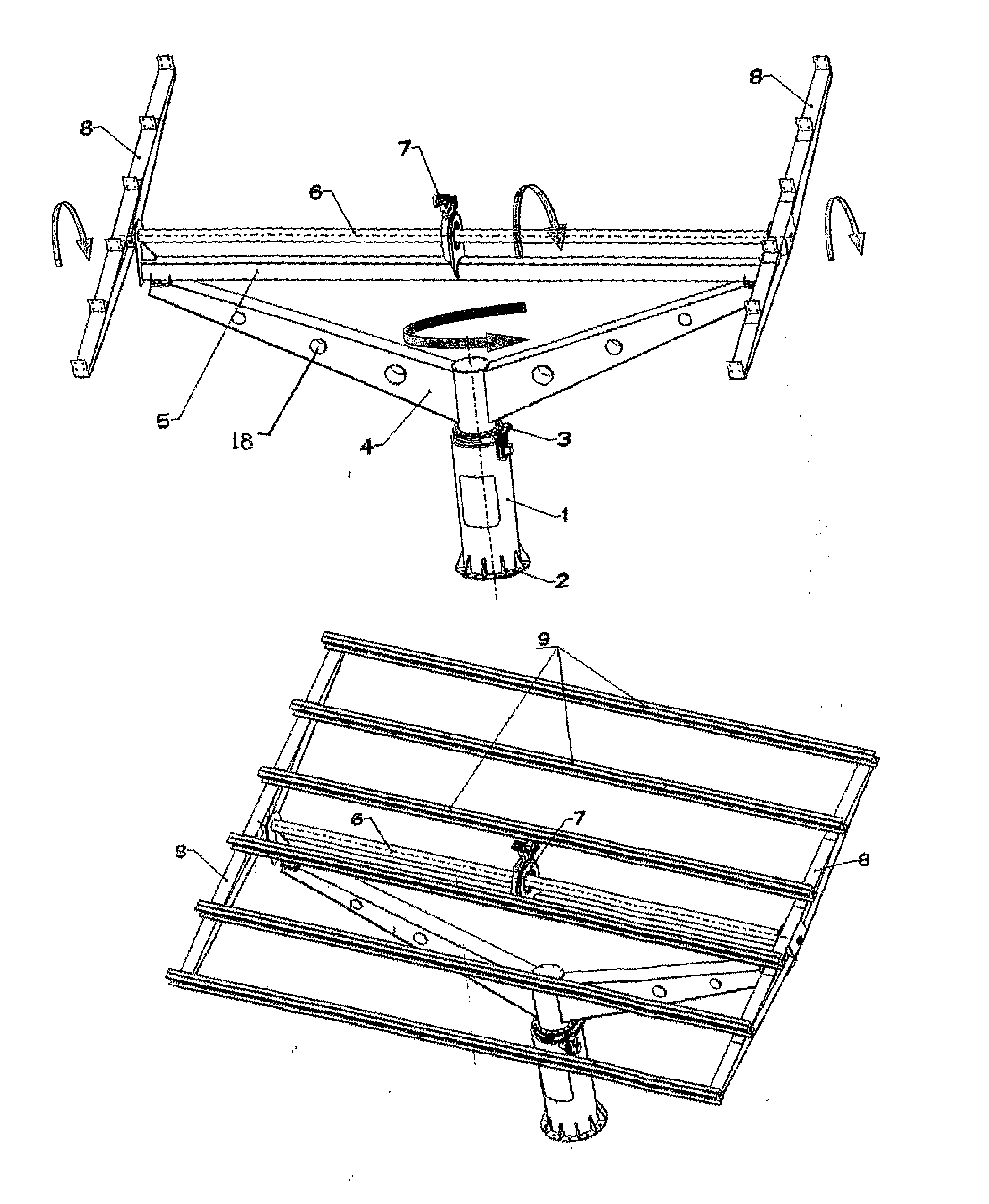
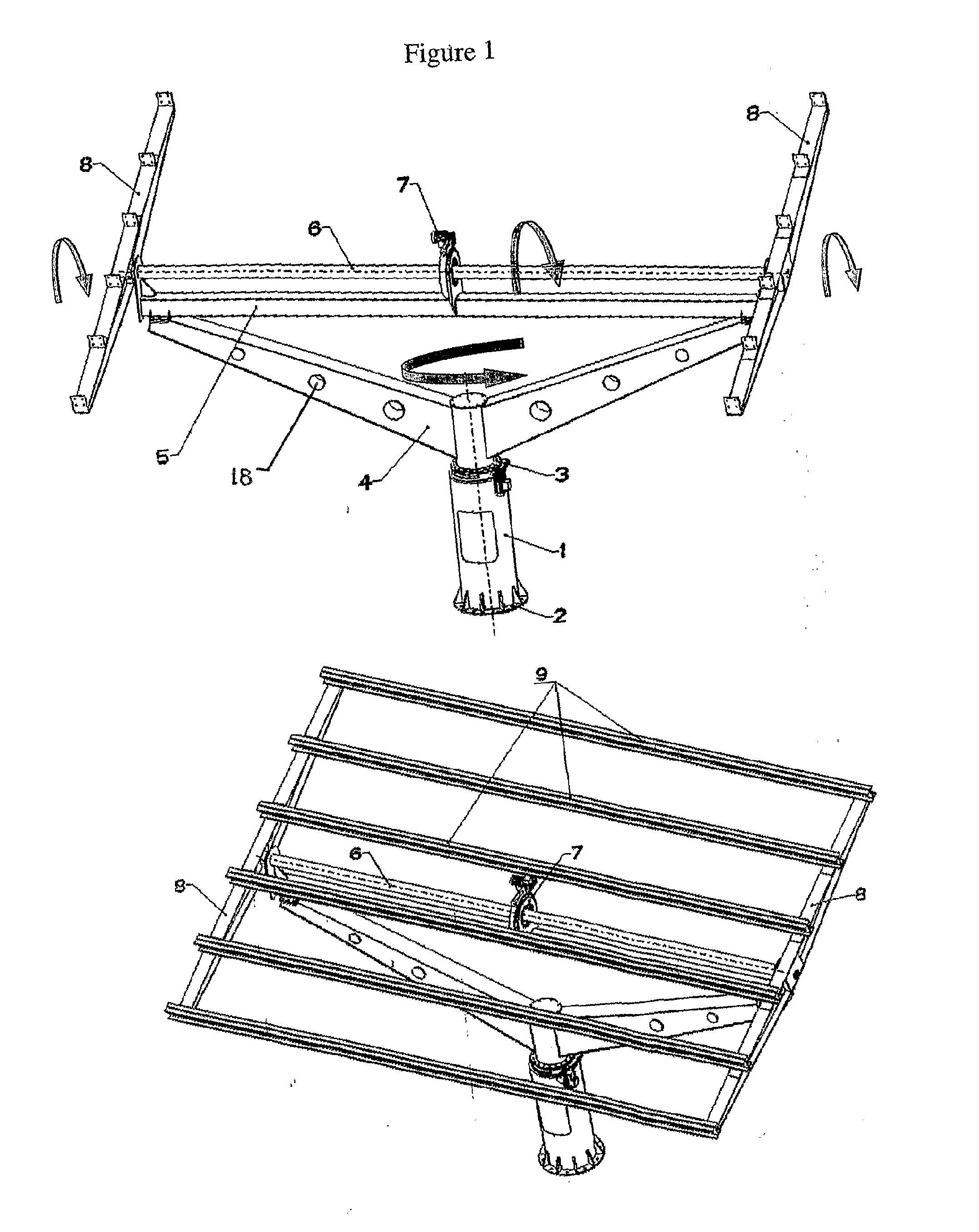
[0020]In particular, FIG. 1 shows the present invention which is a photovoltaic panel rotating around two axis simultaneously, i.e. around a horizontal axis (North-South direction) and around a vertical axis (East-West direction).

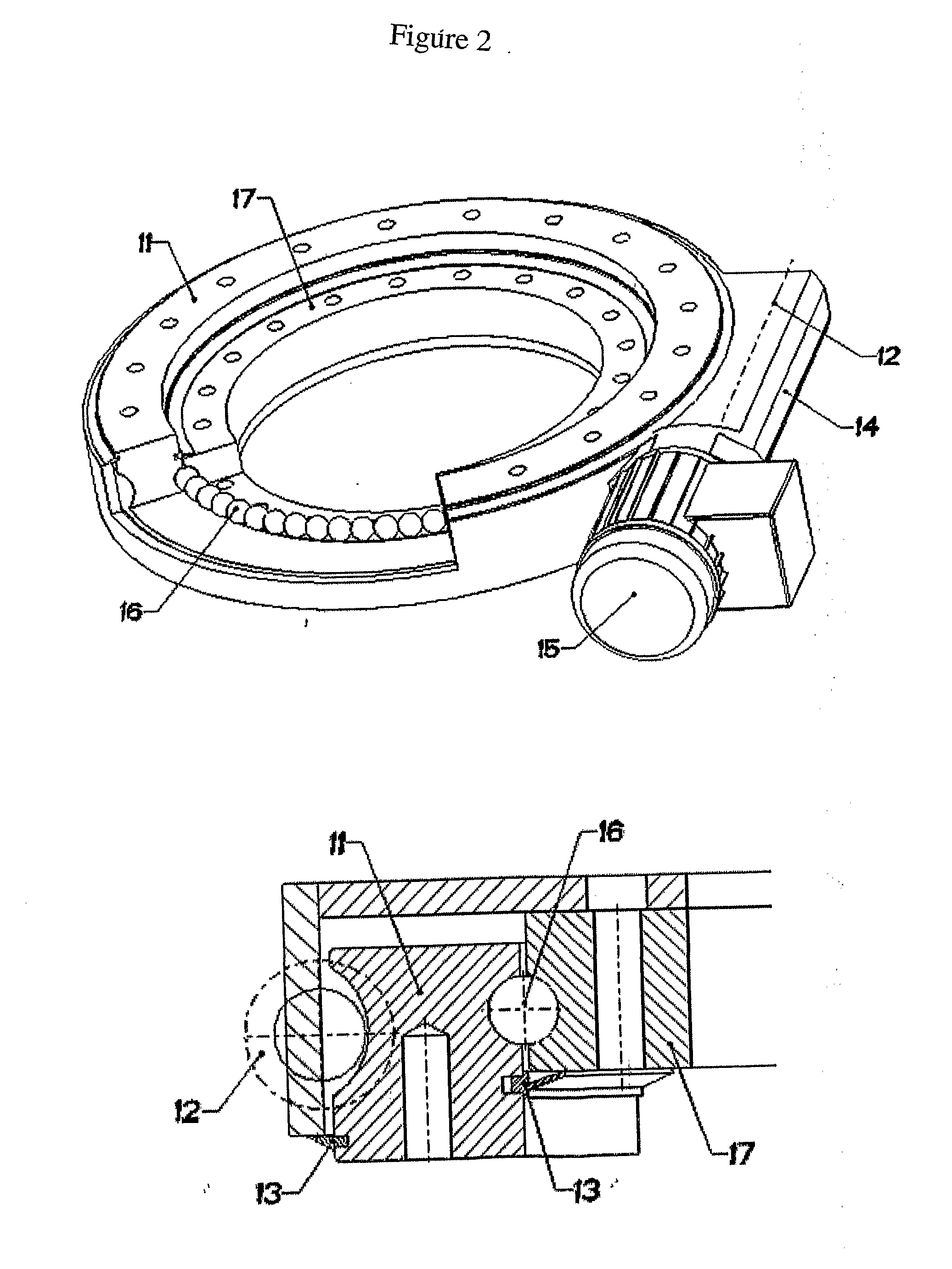
[0021]It constitutes an assembly comprising the following main parts: The tower (1) made of steel pipe with seam and welded steel base of circular profile (2) which is provided with ribs and slots used for the anchorage and the seat of the assembly. The upper part of the tower is assembled by screws, the first drive mechanism (3) with ball bearings (16) for the rotation of the upper part around a vertical axis (East-West directio...


PUM


Abstract

A Photovoltaic panel support base rotating simultaneously around two axes, i.e. around an horizontal axis (North-South direction) for the continuous correction of the swivel angle (β), and around a vertical axis (East-West direction) for the continuous correction of the hour angle (ω), the solar deviation (δ) and the azimuthal surface (γ). The assembly comprises the tower (1), the base (2) with round profile, used for the anchorage and the seat of the assembly, the first drive mechanism (3) with ball bearings (16) for the rotation of the upper part around a vertical axis, the cantilevers' support assembly (4) of V shape, the rod (5), the second mechanism (7) for the rotation of the photovoltaic panels plane around an horizontal axis, the rotation axis (6) of the photovoltaic panels plane, the beams (8) of changing thin walled profile H and the series of transverse thin walled beams (9) of U profile. The frames of the photovoltaic panels rest on the frame formed by the U-shaped beams. The strong wind which falls at the photovoltaic panel plane is received and transmitted to the inner part of the construction, from one hand by the beams assembly (8) of shape H and from the other by the V-shaped assembly of the cantilevers (4). The strong forces' flow to the increasing profiles of the two assemblies (8) and (4) significantly decreases their strength to the inner part of the construction and as a result the two rotating drive mechanisms (3) and (7) substantially receive minimum dynamic stressing having the form of contact voltages (Hertz) created to their ball bearings (16). The electric motors of the two rotation mechanisms are driven by means of satellite control in order for the combination of β, ω, δ and γ to provide the instantly desired result cos θ=1 or Θ=0, i.e. the incident solar radiation to always be vertical with regard to the panels plane.

Description

CROSS-REFERENCE TO RELATED APPLICATIONStatement Regarding Federally Sponsored Research or Development[0001]n / aFIELD OF THE INVENTION[0002]The present invention relates to a method and system for a photovoltaic panel support base construction rotating simultaneously around two axes, i.e. around an horizontal axis (North-South direction) for the continuous correction of the swivel angle (β), and around a vertical axis (East-West direction) for the continuous correction of the hour angle (ω), the solar deviation (δ) and the azimuthal surface (γ), providing a photovoltaic panel plane pivoted on two axes with continuous and adjustable drive, in order for the incident solar radiation to be as vertical as possible with regard to the panels surface.[0003]The incidence angle Θ of the solar radiation to a sloping surface is the angle between the incident solar rays and the vertical with regard to the surface. The incidence angle Θ of the solar radiation with regard to a sloping surface is est...

Claims


Application Information

Patent Timeline
IPC IPC(8): H01L31/052F24S50/20
CPCF24J2/5232F24J2/542H02S20/00Y02E10/47Y02E10/50F24J2002/5482H02S20/30F24S2030/15F24S30/452F24S25/12F24S50/20
Inventor DRITSAS, VASILEIOS
Owner DRITSAS VASILEIOS
Learn More