Camera module

Active Publication Date: 2008-12-04
MITSUMI ELECTRIC CO LTD
View PDF6 Cites 16 Cited by
  • Summary
  • Abstract
  • Description
  • Claims
  • Application Information

AI Technical Summary

Benefits of technology

[0015]The present invention has been made in view of the problem described above, and therefore it is an object of the present invention to provi

Problems solved by technology

Therefore, when the small-sized electronic apparatuses equipped with the camera module is dropped by an accident, there is a case that dust which is formed from glass filler or synthetic resins chipped f

Method used


Image

  • Camera module
  • Camera module
  • Camera module

Examples


Example

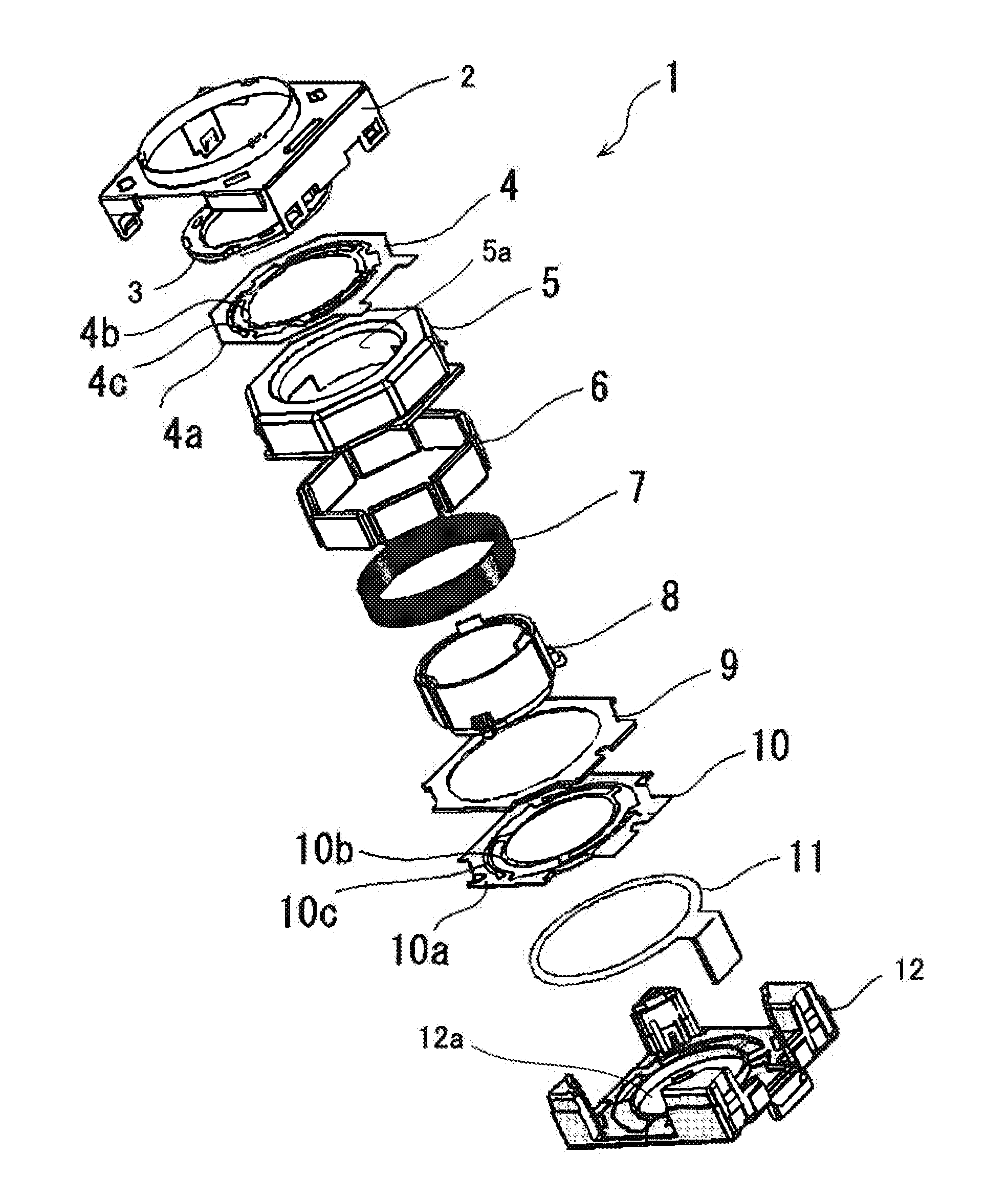
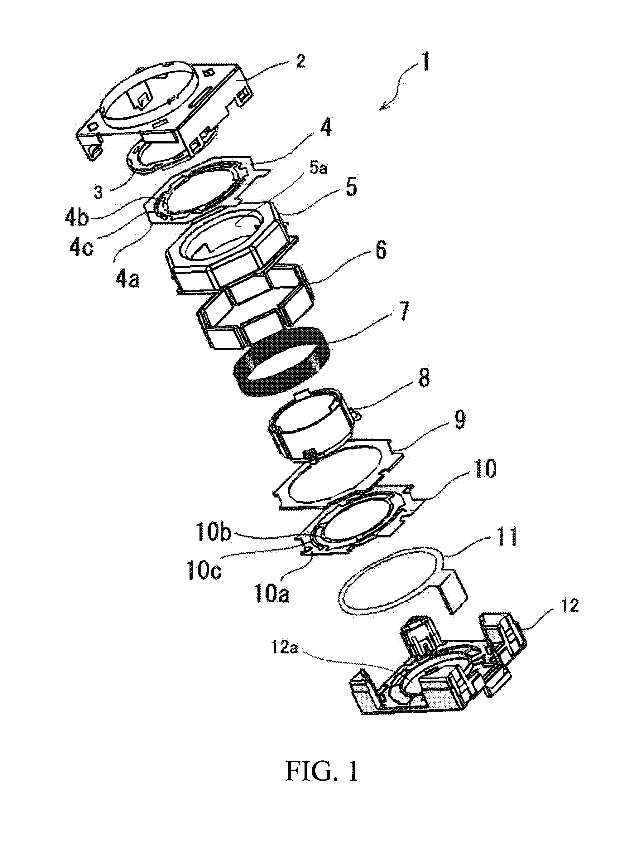
[0025]A camera module according to an embodiment of the present invention will be described below with reference to the accompanying drawing.

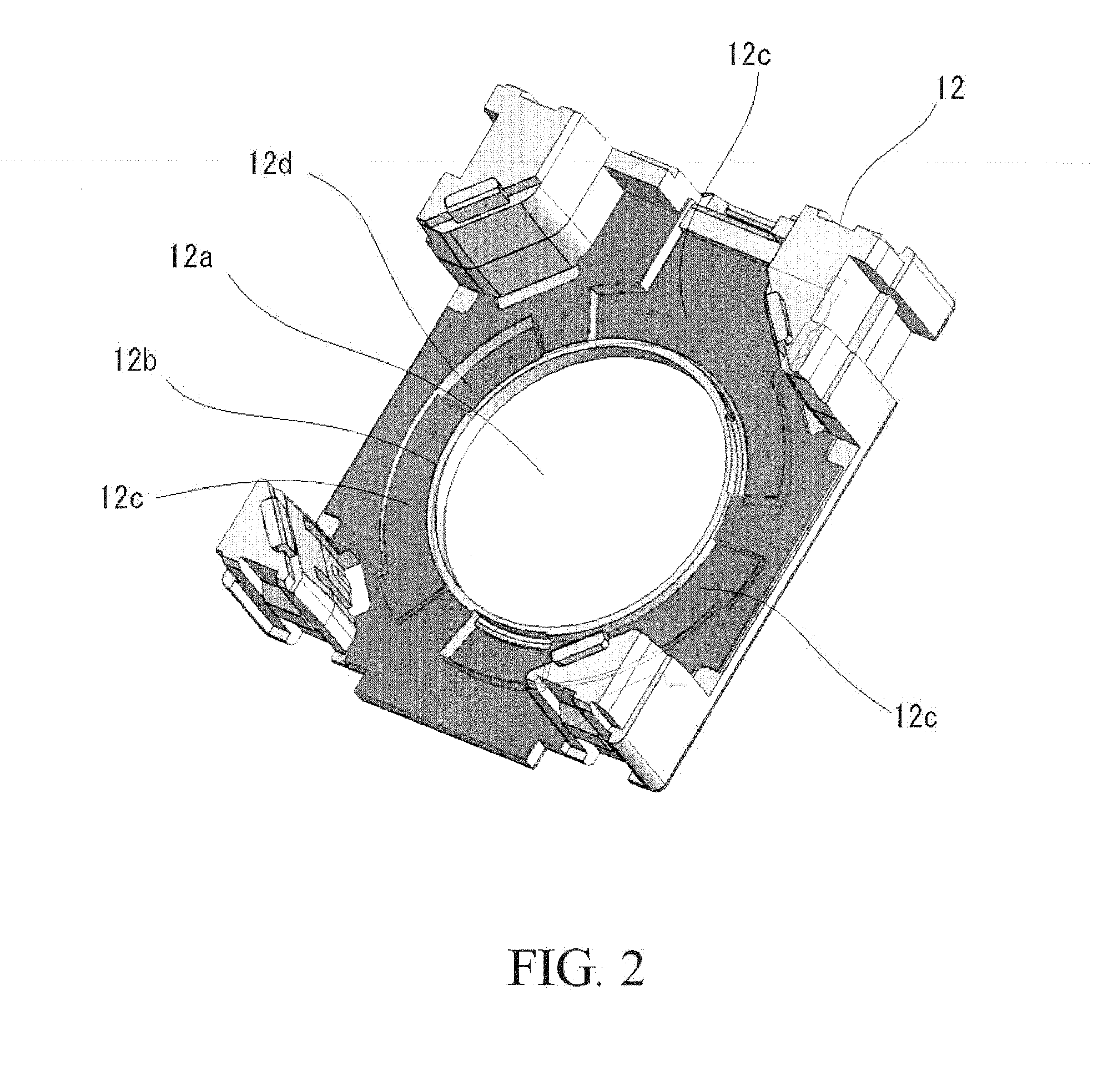
[0026]The camera module according to this embodiment comprises: a lens unit (not shown) which constitutes an optical system of the camera module; a holder 8 which has a hollow cylindrical portion that houses the lens unit therein and is displaceable along an optical axis direction of the lens unit; a coil 7 having a cylindrical form and provided around the cylindrical portion of the holder 8; a yoke 5 and magnets 6 provided on the yoke 5 for providing a magnetic field to the coil; upper and lower leaf springs 4, 10 for supporting the holder 8 so that the holder 8 is displaceable along an optical axis direction of the lens unit; a base 12 which supports the yoke and has an opening 12a at a center thereof; a cover 2 attached to the base 12 so as to define a space therebetween in which the holder 8 can be displaced; and an imaging element (not sho...


PUM


Abstract

A camera module that can obtain a clear image even in the case where dust is generated inside the camera module due to a shock applied thereto is provided. The camera module includes a base and a cover attached to the base so as to define a space therebetween in which the holder can be displaced. The base has an upper surface which faces the cover, and the upper surface of the base includes a concaved dust collecting portion and a dust falling preventing wall formed on the upper surface so as to surround an entire circumference of an opening of the base, and wherein a surface of the concaved dust collecting portion includes a dust sticking layer to which fallen dust is adapted to stick, whereby when dust is generated in the space between the cover and the base and such dust is fallen onto the upper surface of the base, it is possible to prevent such dust from entering into the opening by the dust falling preventing wall and such dust is stuck to the dust sticking layer of the dust collecting portion provided on the upper surface of the base.

Description

BACKGROUND OF THE INVENTION[0001]1. Field of the Invention[0002]This invention relates to a camera module, and more specifically to a camera module that can be used in small-sized electronic apparatuses such as digital cameras, camera-equipped cellular phones and the like.[0003]2. Description of the Related Art[0004]A camera module having a function of displacing a lens unit in a direction of an optical axis of the lens unit is used in relatively small-sized digital cameras, camera-equipped cellular phones and the like. This function is used for providing an autofocus function and / or zoom function and the like, and is achieved by an interaction between a magnetic field generated by an electrical current flowing in a coil and a magnetic field generated by a yoke and magnets provided on the yoke.[0005]Such a camera module generally includes a barrel which holds the lens unit, a holder which houses the barrel therein, and a pair of leaf springs for supporting the holder so that the hol...

Claims


Application Information

Patent Timeline
IPC IPC(8): G02B27/00
CPCG02B13/001G02B27/0006H02K41/0356
Inventor OSAKA, TOMOHIKOISHIZAWA, TAKASHI
Owner MITSUMI ELECTRIC CO LTD
Why Eureka
Try Eureka