Method of coordinated wireless downlink transmission

a wireless downlink transmission and wireless network technology, applied in wireless communication, wireless commuication services, power management, etc., can solve the problems of limiting rf efficiency and capacity in broadband wireless networks, intercell interference, transmissions received from neighboring base stations perceived as interference, etc., to reduce intercell interference, reduce or eliminate any interference, the effect of maximizing the specified ra

Active Publication Date: 2008-12-04
WSOU INVESTMENTS LLC
View PDF11 Cites 13 Cited by
  • Summary
  • Abstract
  • Description
  • Claims
  • Application Information

AI Technical Summary

Benefits of technology

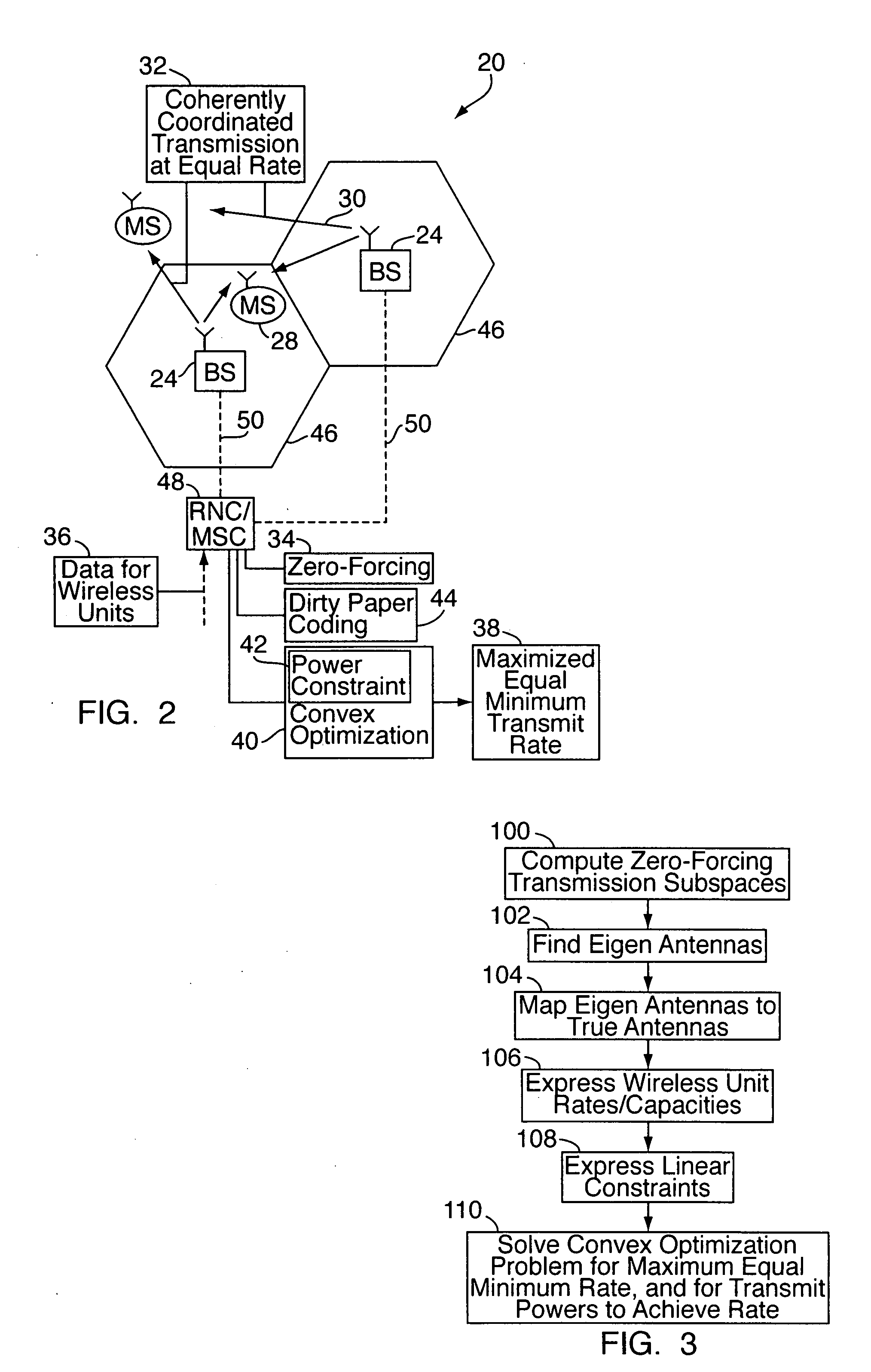
[0006]To reduce intercell interference, an embodiment of the present invention relates to a method of coherently coordinated downlink transmission in a wireless network. The network includes a plurality of interconnected, fixed base stations, each having one or more RF transmission antennas, and a plurality of wireless units. (By “wireless unit,” it is meant mobile phones, wireless PDA's, computerized vehicle navigation systems, wireless devices with high-speed data transfer capabilities, such as those compliant with “3-G” or “4-G” standards, “WiFi”-equipped computer terminals, or the like.) In operation, the base stations transmit signals to the wireless units in a coherently coordinated manner (e.g., signal transmissions are coordinated among the base stations by transmitting data between the base stations for this purpose), for coherent, reinforced reception at the wireless units. In other words, transmissions from the base stations are coordinated such that the desired RF waves received at each wireless unit's particular location constructively add, but cancel out at other locations where they would otherwise constitute interference. The signals are generated based on a zero-forcing operation, e.g., by applying zero-forcing complex antenna weight vectors to data symbols designated for transmission to the wireless units. (In effect, the weight vectors for each wireless unit are selected to be orthogonal to the other wireless units' channels, thereby nulling interference.) For fairness, the signals are transmitted at no less than a specified rate which is common to all of the wireless units, e.g., a minimum rate or, equivalently, a guaranteed common rate.
[0007]In another embodiment, the specified rate (e.g., minimum rate or guaranteed common rate) is determined in view of at least one transmission power constraint of the base stations, e.g., a per-base station power constraint or a per-transmission antenna power constraint. For example, a convex optimization problem (which incorporates a linear power constraint) may be solved to maximize the specified rate. Signals may be transmitted to users at the same specified rate, or at different rates. Also, in regards to the specified rate, there may be one specified rate, or there may be different specified rates for different users, classes of users, transmission / data / QOS (quality of service) types, etc. Rates for different users, classes of users, etc. may be weighted multiples of the specified rate, e.g., multiples of a maximized minimum rate or maximized guaranteed common rate.
[0008]In another embodiment, dirty paper coding is used to generate the coherently coordinated transmission signals, for the cancellation of known interference. Zero-forcing operations are applied to reduce or eliminate any interference still present from the dirty paper coding.
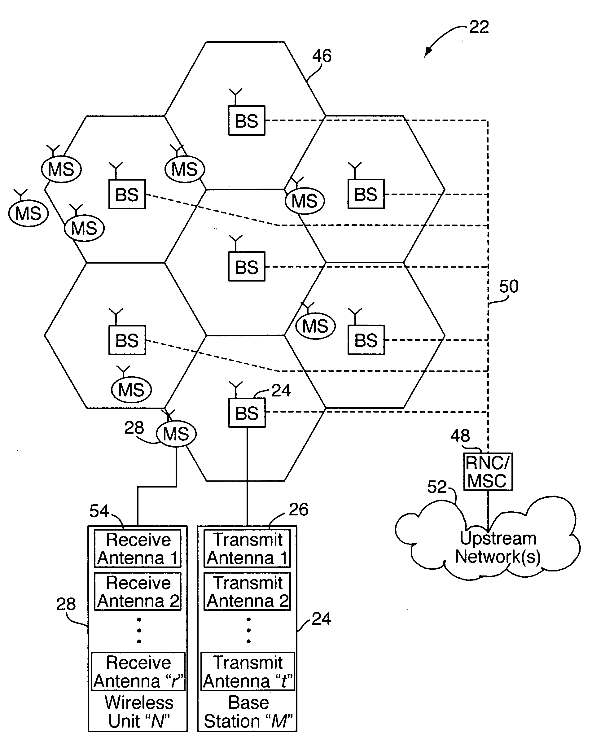
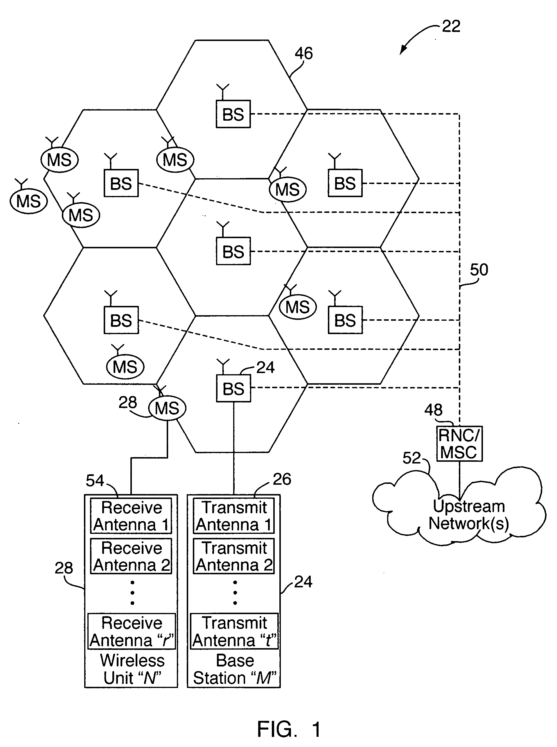
[0009]In another embodiment, the base stations and wireless units each have a plurality of RF antennas for transmitting and receiving signals, respectively. Here, transmission signals are coordinated among the base stations with respect each base station antenna, i.e., each antenna is treated as a separate transmission source for coherently coordinated transmissions to the wireless units. If the wireless units have plural receive antennas, each base station may transmit a plurality of independent symbol streams simultaneously for each wireless unit, where the number of streams corresponds to the number of receive antennas. (It may be the case that the receiver has more antennas than the transmitter, in which case, more generally speaking, the number of symbol streams is less than or equal to the number of receive antennas.)
[0010]The signal-processing scheme for coherently coordinated transmissions may be summarized as including the following steps, according to another embodiment of the present invention. First, zero-forcing transmission subspaces are calculated for the base station transmission antennas. Eigen antennas are found based on the computer subspaces, and are mapped to the true antennas. Wireless unit rates / capacities and linear constraints (e.g., power constraints) are expressed as part of a convex optimization problem, which is solved for maximizing a minimum rate or guaranteed common rate and for the antenna transmission powers to achieve the guaranteed common transmission rate.
[0011]In another embodiment, prior to transmitting signals to the wireless units, the system discards a portion of the active wireless units in the network, for purposes of improving overall system performance. By “discard,” it is meant that coherently coordinated signals are not transmitted to the wireless units so designated, at least temporarily, e.g., until channel conditions change. For illustrative purposes only, an example user loading level is, say, 90%, wherein 10% of active wireless units are assigned to an outage state. “Active” wireless unit refers to a wireless unit that is known to the network.

Problems solved by technology

A major factor limiting RF efficiency and capacity in broadband wireless networks is intercell interference.
The transmissions received from neighboring base stations are perceived as interference by the receiving wireless unit.

Method used


Image

  • Method of coordinated wireless downlink transmission
  • Method of coordinated wireless downlink transmission
  • Method of coordinated wireless downlink transmission

Examples


Embodiment Construction

[0019]Turning to FIGS. 1 and 2 in overview, the present invention relates to a system and method 20 of coordinated downlink transmission in a wireless network 22. The network 22 includes a plurality of interconnected, fixed base stations (“BS”) 24, each having one or more RF transmission antennas 26, and a plurality of wireless units or mobile stations (“MS”) 28. (“Wireless unit” or “mobile station” refer to mobile phones, wireless PDA's, computerized vehicle navigation systems, wireless devices with high-speed data transfer capabilities, such as those compliant with “3-G” or “4-G” standards, “WiFi”-equipped computer terminals, or the like.) In operation, each base station 24 transmits signals 30 to each wireless unit 28 in a coherently coordinated manner 32 (e.g., signal transmissions are coordinated among the base stations by transmitting data between the base stations for this purpose), for coherent, reinforced reception at the wireless units 28. In other words, transmissions fro...


PUM


Abstract

To reduce intercell interference, a method of coherently coordinated downlink transmission in a wireless network involves coordinating transmissions from a plurality of base stations to a plurality of wireless units, for coherent, reinforced reception of the transmitted signals at the wireless units. Thus, transmissions from the base stations are coordinated such that signals received at each wireless unit's particular location constructively add, but cancel out at other locations. The signals are generated based on a zero-forcing operation, e.g., by applying zero-forcing complex antenna weight vectors to data symbols designated for transmission to the wireless units. For fairness, the signals are transmitted at no less than a guaranteed common rate. A convex optimization problem (which incorporates a per-base station power constraint or a per-transmission antenna power constraint) is solved to maximize the guaranteed common rate. Dirty paper coding may also be employed.

Description

FIELD OF THE INVENTION[0001]The present invention relates to communication systems and, more particularly, to methods of radio frequency communications in a wireless network.BACKGROUND OF THE INVENTION[0002]Wireless, radio frequency (“RF”) communication systems enable people to communicate with one another over long distances without having to access landline-connected devices such as conventional telephones. In a typical cellular telecommunications network (e.g., mobile phone network), an area of land covered by the network is geographically divided into a number of cells or sectors, which are typically contiguous and which together define the coverage area of the network. Each cell is served by a base station, which includes one or more fixed / stationary transceivers and antennae for wireless communications with a set of distributed wireless units (e.g., mobile phones) that provide service to the network's end-user subscribers. The base stations are in turn connected (e.g., by way ...

Claims


Application Information

Patent Timeline
Patent Type & Authority Applications(United States)
IPC IPC(8): H04Q7/20H04W16/12H04W72/04
CPCH04W16/12H04W52/267H04W52/367H04W52/42
Inventor FOSCHINI, GERARD J.
Owner WSOU INVESTMENTS LLC
Why Eureka
Try Eureka