Method and device for resource allocation control in radio communications system

a radio communication system and resource allocation technology, applied in the field of radio communication systems, can solve the problems of delay in processing, interference of ul-sch transmission by pach transmission in one of the cells, delay in call setup in the neighboring cell, etc., and achieve the effect of reducing inter-cell interferen

Active Publication Date: 2008-10-30
NEC CORP
View PDF15 Cites 42 Cited by
  • Summary
  • Abstract
  • Description
  • Claims
  • Application Information

AI Technical Summary

Benefits of technology

[0015]An object of the present invention is to provide a resource allocation control method and device that can reduce inter-cell interference.
[0017]According to the present invention, in the resources of a cell, a buffer resource is set within a predetermined resource area corresponding to a control resource used in a neighboring cell, whereby inter-cell interference can be reduced.

Problems solved by technology

However, in the case where different control entities individually perform resource allocation in neighboring cells, there is a possibility that a PACH transmission in one of the cells interferes with an UL-SCH transmission in the other cell.
This is because, if the data transmission in the certain cell interferes with the RACH transmission in the neighboring cell, call setup will be delayed in the neighboring cell.
In the case where RACH transmission is required prior to the start of other processing as well, a similar effect is caused: specifically, the processing is delayed due to strong uplink interference of a high-speed uplink data transmission to the RACH transmission.
However, if the cells A and B are neighboring cells as shown in FIG. 1A and the frequency band and timing of data transmission performed by a mobile station UE1 located in the cell A coincide with those of RACH transmission performed by a mobile station UE2 located in the cell B, then the possibility is large that interference as shown in FIG. 2B occurs.
As described above, the possibility increases that the start of communication of the mobile station UE2 is greatly delayed due to a collision with the UL-SCH transmission.
However, according to this method, a RACH resource cannot be allocated periodically, leading to unstable access from a mobile station UE to a base station eNB, resulting in a high possibility of a long delay.
Moreover, since a resource making small interference is generally allocated to data transmission, the fact that the smallest-interference resource is allocated to RACH transmission may cause larger interference in reverse, making it easier for collision to occur.
Such a problem concerns not only the LTE, but may exist in general radio communications systems using an access scheme (FTDMA) based on a frequency-divided and time-divided resource structure.

Method used


Image

  • Method and device for resource allocation control in radio communications system
  • Method and device for resource allocation control in radio communications system
  • Method and device for resource allocation control in radio communications system

Examples


examples

5. System Structure

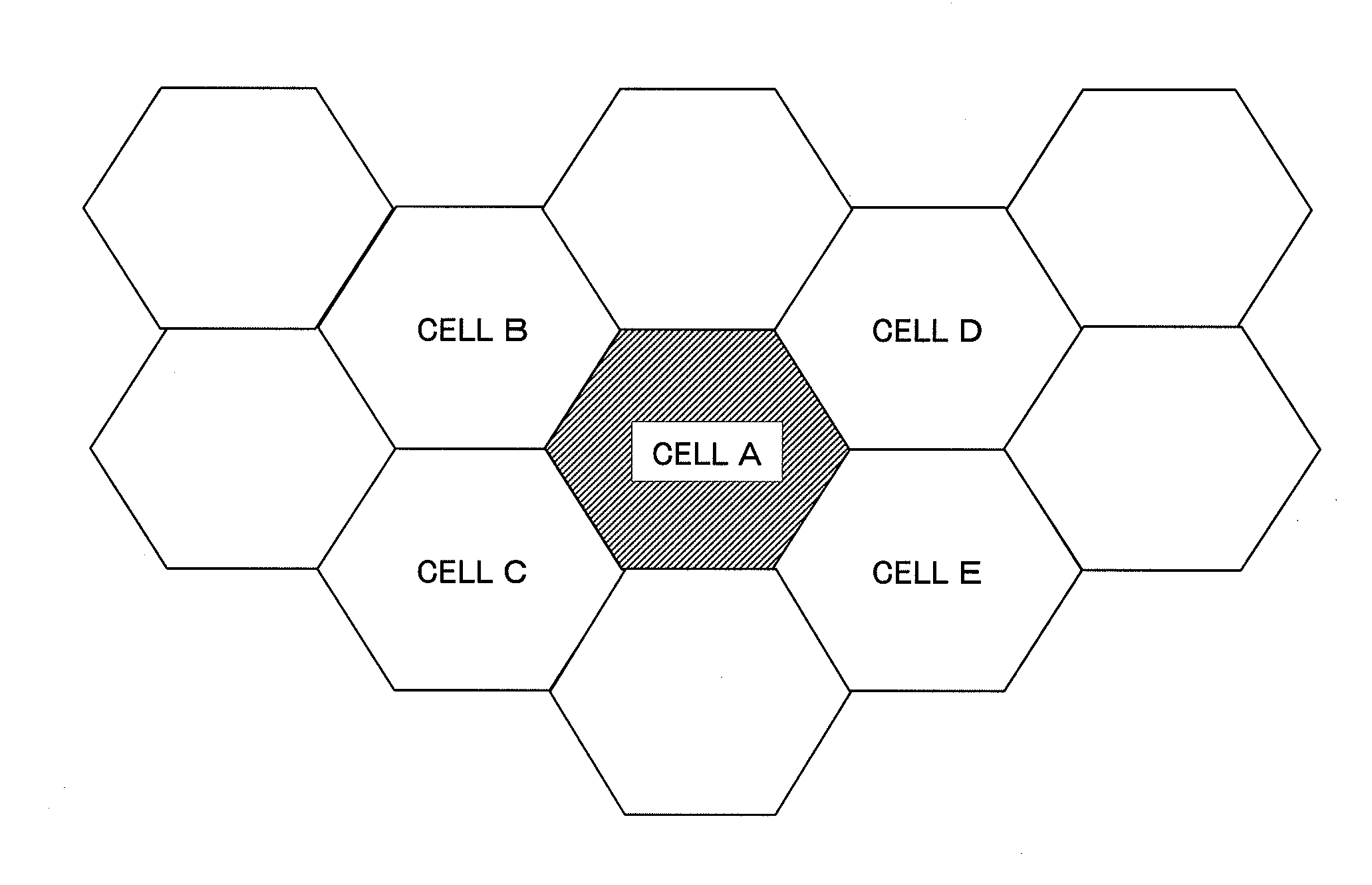
[0064]FIG. 8 is a block diagram showing a schematic structure of a radio communications system including radio communication devices implementing the present invention. Here, it is assumed that a plurality of radio communication devices including radio communication devices 10 and 11 are communicably connected to each other through a network 12. In addition, it is assumed that the radio communication devices 10 and 11 control cells A and B respectively, and that each of the cells A and B has the resource structure shown in FIG. 4. Each radio communication device performs UL-SCH scheduling by adopting any one of the resource allocation control methods according to the above-described first to third exemplary embodiments.

[0065]The plurality of radio communication devices connected through the network 12 may be included in a single base station eNB, or each radio communication device may be a single base station eNB. In any case, when a plurality of mobile stations U...

first exemplary embodiment

7. Operation of First Exemplary Embodiment

[0079]FIG. 12 is a flow chart showing the resource allocation control method according to the first exemplary embodiment of the present invention. Base stations eNB respectively controlling neighboring cells share RACH resource information on the respective cells with each other, by each base station eNB reporting, through the RACH resource control section 102, RACH scheduling information and currently occupied RACH resources to the other base station eNB (Step S301). Subsequently, the buffer resource setting section 105 of each base station eNB determines whether or not the level of RACH interference obtained from the RACH-related information measurement section 103 is larger than a predetermined threshold value (Step S302). When the level of RACH interference is larger (Step S302: YES), the buffer resource setting section 105 sets buffer resources for its neighboring cell, based on the RACH resource information on the neighboring cell in q...

second exemplary embodiment

8. Operation of Second Exemplary Embodiment

[0080]According to the second exemplary embodiment, a base station eNB operates as follows.[0081]The base station eNB reports RACH scheduling information currently in use to a neighboring cell.[0082]The base station eNB sets resources corresponding to the RACH resources and nearby resources of the neighboring cell, as uplink buffer resources. These uplink buffer resources can be used by a VoIP mobile station UE, or a mobile station UE that is located around the center of the cell and therefore has high path loss to the neighboring cell.

[0083]More specifically, RACH and UL-SCH resource allocation control between cells is performed as follows.

[0084]FIG. 13 is a flow chart showing the resource allocation control method according to the second exemplary embodiment of the present invention. Base stations eNB respectively controlling neighboring cells share RACH resource information on the respective cells with each other, by each base station eN...


PUM


Abstract

A resource allocation control method and device that can reduce inter-cell interference in a radio communications system are provided. According to a method for resource allocation control between a plurality of cells in a radio communications system, radio communication devices respectively controlling at least two cells notify information about control resources of its own cell to each other. In the resources of its own cell, each of the radio communication devices sets a buffer resource within a predetermined resource range corresponding to a control resource of the other cell. At a request for information transmission in its own cell, each of the radio communication devices restricts the allocation of the set buffer resource.

Description

BACKGROUND OF THE INVENTION[0001]1. Field of the Invention[0002]This application is based upon and claims the benefit of priority from Japanese Patent Application No. 2007-120377, filed on Apr. 28, 2007, the disclosure of which is incorporated herein in its entirety by reference.[0003]The present invention relates to a radio communications system having a plurality of radio zones (hereinafter, referred to as cells) and, more particularly, to a method and device for resource allocation control in the system.[0004]2. Description of the Related Art[0005]In a mobile communications system, for a base station and a mobile station to perform data communication, they need to establish synchronization between them in advance. Since initial access from the mobile station in particular is not always in synchronization, the base station requires some procedure for uplink synchronization with the mobile station.[0006]In LTE (Long Term Evolution), which is being standardized by the 3rd generation...

Claims


Application Information

Patent Timeline
Patent Type & Authority Applications(United States)
IPC IPC(8): H04Q7/20H04M1/00H04W16/10H04W72/04H04W72/08H04W74/08
CPCH04W16/10H04W72/04H04W72/0426H04W72/27
Inventor LEE, JINSOCKHAMABE, KOJIRO
Owner NEC CORP
Why Eureka
Try Eureka