
Beacon signaling in a wireless system

Inactive Publication Date: 2008-04-29
QUALCOMM INC
View PDF66 Cites 48 Cited by
  • Summary
  • Abstract
  • Description
  • Claims
  • Application Information

AI Technical Summary

Benefits of technology

[0029]In some embodiments, the wireless terminal estimates its channel condition characteristics and notifies the base station, such that the base station can make sensible scheduling decisions in terms of power and burst data rate allocation. The channel condition information may include information distinguishing between inter-sector interference and other interference. In accordance with the invention, the base station's scheduler may use the reported channel condition characteristics of the wireless terminals including power information, signal strength, and SIR to match wireless terminals to appropriate channels in each sector. Decisions on providing additional power or allocating segments for a wireless terminal to a channel having high power can be made based on the indication of inter-sector interference relative to other interference. In this manner, wireless terminals which can benefit from higher transmission power, e.g., those subject to low inter-sector interference, can be allocated to high power channels in a preferential manner over wireless terminals subject to comparatively high inter-sector interference. Assignment of high power channel segments can be used to load balance the system, improve or optimize system performance and / or increase throughput capability by evaluating and reducing inter-sector and inter-cell interference.
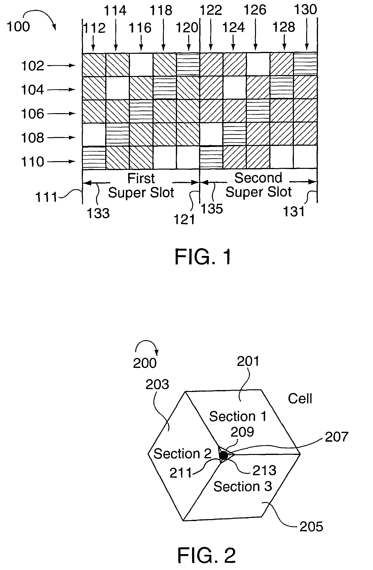
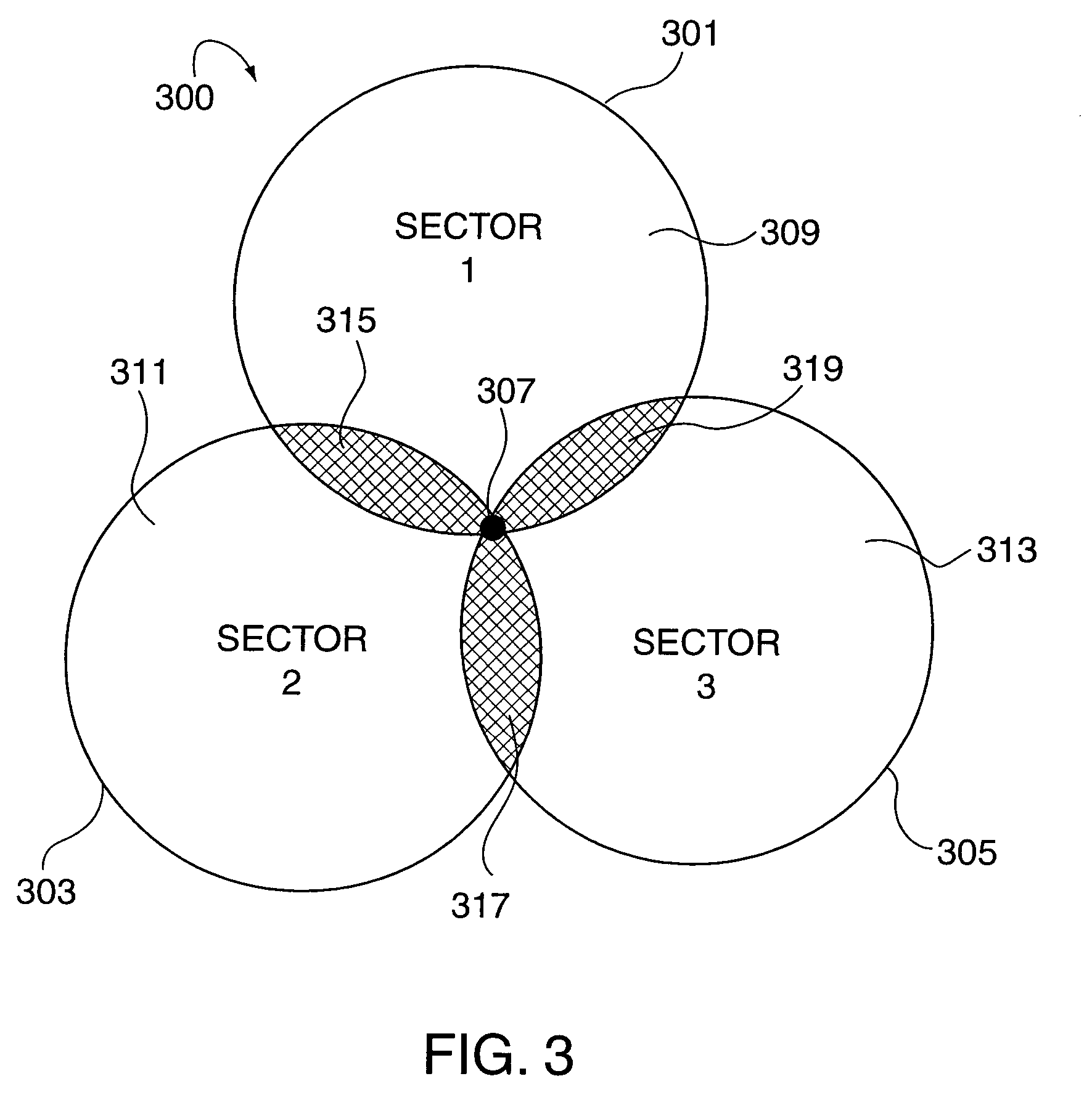
[0030]In accordance with one embodiment of the invention, if a wireless terminal is operating within a sector's cell boundary region and assigned a channel segment, the cell's scheduler may leave the tones corresponding to the channel segment in the sector adjacent the boundary region unassigned to reduce or eliminate the inter-sector interference. In accordance with the invention, sectorization isolation between wireless terminals in non-sector boundary areas may be managed by the scheduler's selective assignment of channel segments corresponding to channels with different power levels to different wireless terminals. Low power channels segments are normally assigned to wireless terminals near the transmitter while high power channels segments are assigned to wireless terminals far from the base station. The number of low power channels in a sector normally exceeds the number of high power channels with, in many cases, more of the sector's total transmission power being allocated to the relatively few high power channels than the large number of low power channels.
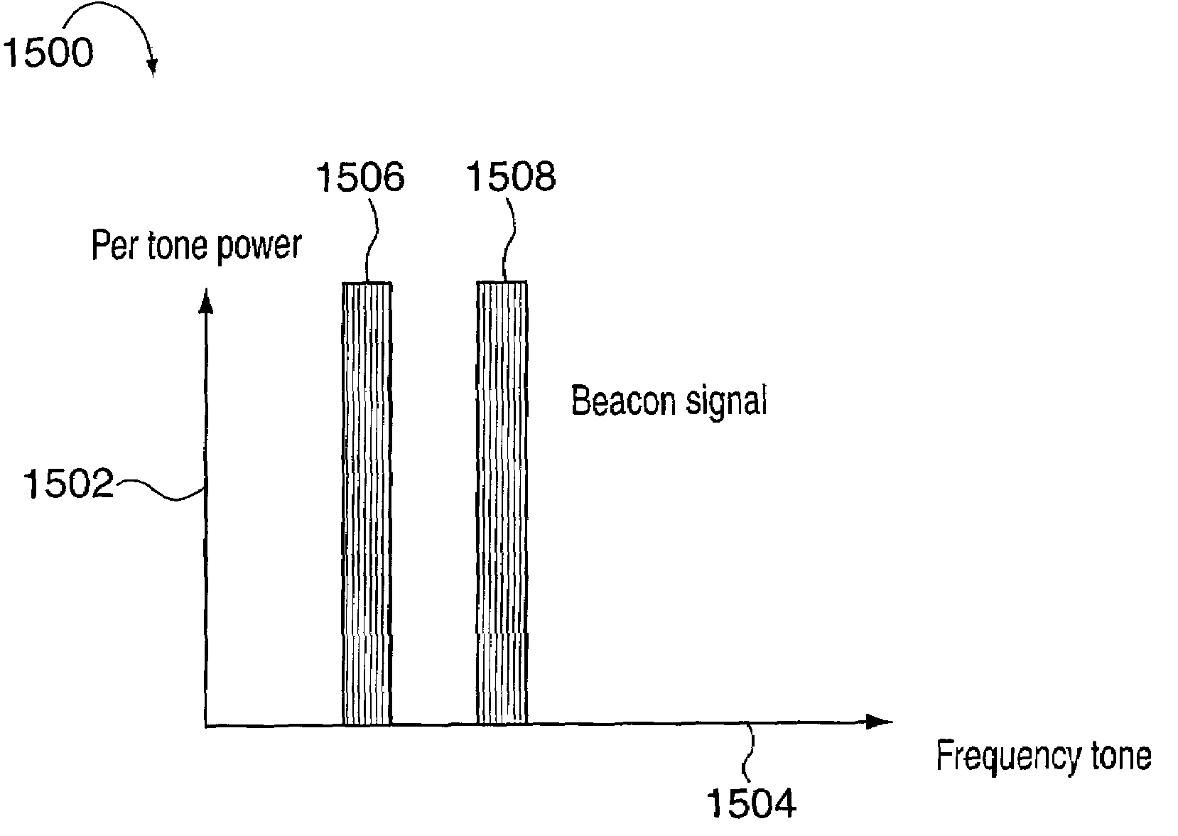
[0032]In one embodiment of the invention, the type of beacon transmitted varies as a function of transmission time, e.g., alternates in the time domain. In another embodiment of the invention, the beacon frequency tone assignments may be reconfigured if a failure or problem occurs at a specific tone frequency. By utilizing both the time and frequency domain to vary the beacon signal transmissions and the information conveyed, a large amount of information may be conveyed to the mobiles in an efficient manner. This information may be used, e.g., to determine the sector / cell location of the mobile, offload some of the functions required by the pilot such as e.g. synchronization to superslot boundaries, reduce the time required for pilot punch through, evaluate reception strength, and provide useful information to predict and improve the efficiency of hand-offs between sectors and cells.

Problems solved by technology

Unfortunately, ideal signal separation is not possible in the real world, which generally complicates the use of sectorization in some systems.
However interference between the sectors due to the limited antenna isolation and reflection from objects can limit the actual capacity gains over an omni cell.

Method used


Image

  • Beacon signaling in a wireless system
  • Beacon signaling in a wireless system
  • Beacon signaling in a wireless system

Examples


Embodiment Construction

[0058]With the OFDM spread spectrum system, the tones used in a given cell are all orthogonal. Therefore, the data hopping sequences and the physical channels do not interfere with each other. Given the wireless channel propagation characteristics, depending on its location, a wireless terminal may experience a large dynamic range of channel conditions measured in terms of signal-to-interference ratio (SIR) or signal-to-noise ratio (SNR). Such a property can be exploited to enhance the system capacity. For example, in accordance with the invention, a scheduler may optimally balance the power allocation in the traffic channel by serving simultaneously wireless terminals with dramatically different wireless channel conditions. In that case, a wireless terminal with a bad wireless channel condition may be allocated with a large portion of transmission power and possibly a small portion of bandwidth thereby gaining service robustness, while another wireless terminal with a good wireless...


PUM


Abstract

A few high power tones used for synchronization and / or other purposes are transmitted in a FDM system during a period of time into a region, e.g., sector of a cell, e.g., a symbol transmission time period. During normal data transmission symbol periods signals are transmitted using at least 10 tones, e.g., per symbol time. Less than 5 high power signals are transmitted in a symbol time with at least 80% the maximum total transmitter power used for transmitting into said region being allocated to the high power signals where the maximum total transmitter power is determined from a period of time which may includes one or more data and / or high power tone transmission periods. When the high power tones are transmitted at most 20% of transmitter power used for transmitting into the region is available for transmitting other tones with the power normally being distributed among multiple tones. Often some tones which would be transmitted in a symbol time go unused during transmission of the high power signals.

Description

RELATED APPLICATIONS[0001]The present invention claims the benefit of U.S. Provisional Patent No. 60 / 406,076 filed Aug. 26, 2002, and is a continuation-in-part of U.S. patent application Ser. No. 10 / 641,399 filed Aug. 13, 2003 now U.S. Pat. No. 6,985,498.BACKGROUND OF THE INVENTION[0002]Spread spectrum OFDM (orthogonal frequency division multiplexing) multiple access, is one example of a spectrally efficient wireless communications technology. OFDM can be used to provide wireless communication services.[0003]In OFDM spread spectrum system, the total spectral bandwidth is normally divided into a number of orthogonal tones, e.g. subcarrier frequencies. In a cellular network, the same bandwidth is often reused in all the cells of the system. Those tones hop across the bandwidth for the purpose of channel (frequency) diversity and interference averaging. Tone hopping follows predefined tone hopping sequences so that the hopped tones of a given cell do not collide with each other. The to...

Claims


Application Information

Patent Timeline
IPC IPC(8): H04J4/00H04B7/005H04B7/12H04L27/26H04W52/34H04W52/42H04W56/00
CPCH04W52/34H04B7/12H04L27/2662H04W52/42H04J1/00H04J3/06H04W84/10
Inventor LAROIA, RAJIVLANE, FRANK A.LI, JUNYI
Owner QUALCOMM INC
Learn More