Construction method for girder in bridge, crane for pulling up girder, vehicle for carring girder, and girder used for the same

Inactive Publication Date: 2008-12-11
SAMSUNG C&T CORP
View PDF11 Cites 21 Cited by
  • Summary
  • Abstract
  • Description
  • Claims
  • Application Information

AI Technical Summary

Benefits of technology

[0034]According to a fourth aspect, there is provided a temporary girder used to the construction method comprising: a temporary girder moving base portion installed on a lower surface of the temporary girder so as to be movable back and forth, and installed on an upper surface of the front coping or the next front coping, for preventing downward deformation of the temporary girder being moved towards a front side of the front coping; and a moving base portion driving device for applying a driving force to the temporary girder moving base portion in back and forth directions.
[0035]According to a fifth aspect, there is provided a temporary girder used to the construction met

Problems solved by technology

However, the conventional method has a problem that the quality of the construction structure is greatly influenced by surrounding circumstances.
The method may have a problem that constructing equipment has to be additionally prepared near

Method used


Image

  • Construction method for girder in bridge, crane for pulling up girder, vehicle for carring girder, and girder used for the same
  • Construction method for girder in bridge, crane for pulling up girder, vehicle for carring girder, and girder used for the same
  • Construction method for girder in bridge, crane for pulling up girder, vehicle for carring girder, and girder used for the same

Examples


Embodiment Construction

[0067]Hereinafter, a construction method for a girder in a bridge, a crane for pulling up a girder, a temporary girder, a vehicle for carriage a girder, and a girder used for the same will be explained in more detail with reference to the attached drawings.

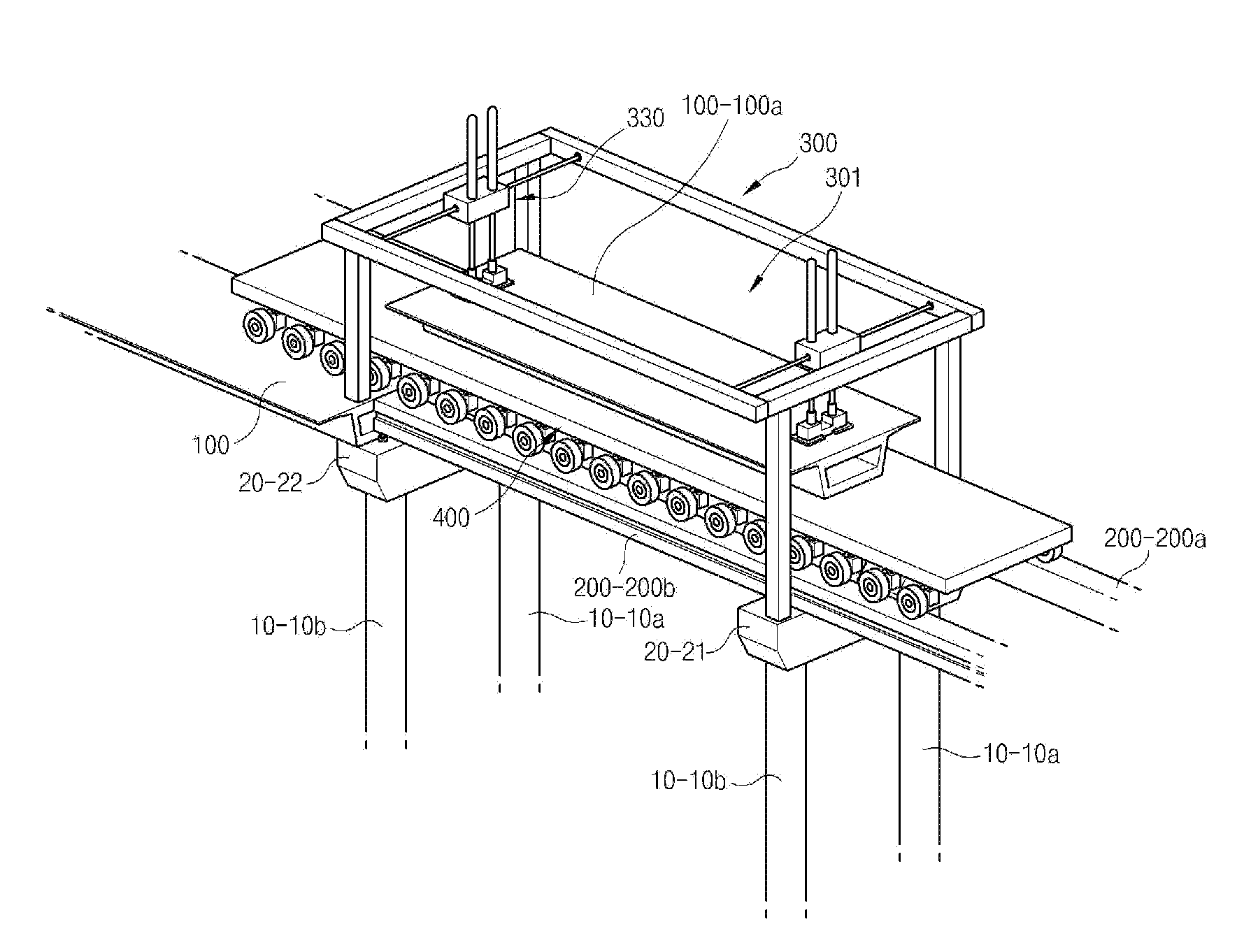
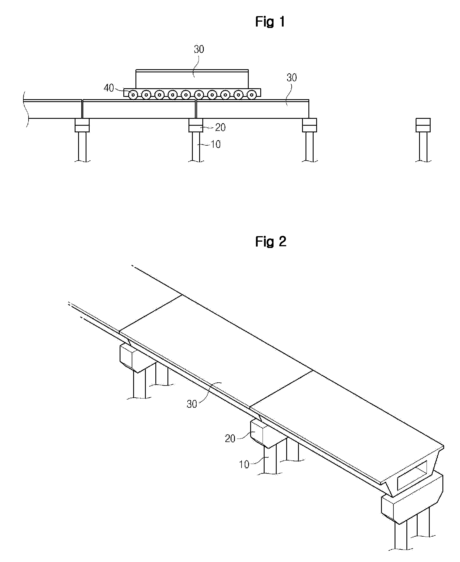
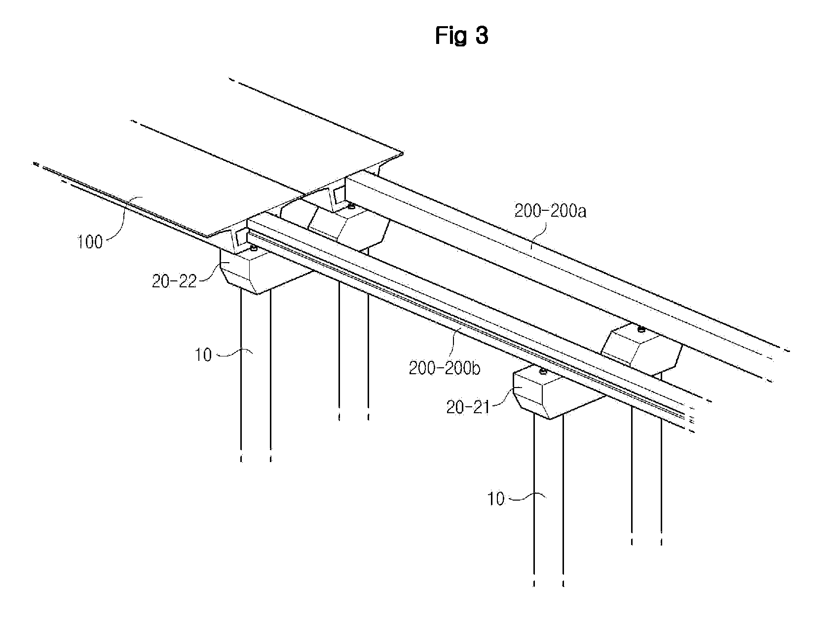
[0068]FIGS. 3 to 10 are mimetic diagrams showing a construction method for a girder in a bridge according to the present invention.

[0069]As shown, in the present invention, a plurality of piers 10 are installed in an interval in a longitudinal direction of the bridge. A plurality of copings 20 are installed on the piers 10, and a plurality of girders 100 respectively installed between the piers are installed on the copings.

[0070]The construction method will be explained according to a construction order.

[0071]First, at least one temporary girder 200 on the front coping 21 of the copings 20 and the rear coping 22 of the copings 20 where the plurality of girders 100 are to be settled (a step of installing at least one temporary gird...


PUM


Abstract

A construction method for a girder in a bridge which a plurality of piers are installed in an interval in a longitudinal direction of the bridge, a plurality of copings are installed on the piers, and a plurality of girders respectively installed between the piers are installed on the copings, the method comprising the steps of: installing at least one temporary girder on a front coping of the copings and a rear coping adjacent to the rear coping of the copings; installing a crane for pulling up a girder having a girder pulling up space therein guided by the temporary girder; providing with a girder by a pre-cast method so as to install a girder on the front coping and the rear coping; providing with a vehicle for carrying a girder, the vehicle being constituted so that load of a girder to the piers carried by the vehicle is distributed to the piers through the upper surface of the girders installed in advance; introducing the vehicle carrying a first girder moving along a guide of the temporary girder to a girder pulling up space of the crane; pulling up the first girder by the crane; drawing out the vehicle backward from the girder pulling up space; moving a first temporary girder of the temporary girders from a position where the first girder is to be installed to a front of the front coping of the one of the copings and installing the first temporary girder on a next front coping installed in a next front of the front coping and the front coping; and settling the first girder on the front coping and the rear coping by the crane is disclosed.

Description

FIELD OF THE INVENTION[0001]The present invention relates to a construction field, and more particularly, to a construction method for a girder in a bridge, a crane for pulling up a girder, a vehicle for carrying a girder, and a girder used for the same, capable of installing a girder on a pier for a bridge for building a bridge.BACKGROUND OF THE INVENTION[0002]In the conventional art, a construction structure is built by pouring concrete after installing a mold and reinforcements on the spot. However, the conventional method has a problem that the quality of the construction structure is greatly influenced by surrounding circumstances.[0003]Accordingly, a pre-cast method is being actively supposed, by which members of a structure are provided in advance, and the members are an installed in the working place. The method has an advantage that the quality of the structure can be ensured regardless of the surrounding circumstances.[0004]The method may have a problem that constructing e...

Claims


Application Information

Patent Timeline
IPC IPC(8): E01D21/00
CPCB66C17/06E01D21/06E01D21/00B66C6/00E01D2/00
Inventor KANG, DONG-OKYOON, MAN-GEUNSHIN, HYUN-YANGKIM, YEONG-SEON
Owner SAMSUNG C&T CORP
Why Eureka
Try Eureka