Pile splicing fixing device adopting pile planting method

A technology of fixing device and fixing rod, applied in sheet pile wall, construction, infrastructure engineering and other directions, can solve the problem of downward deformation of anti-slip rubber material, increased labor intensity of operators, and unguaranteed service life of pile fixing device, etc. problem, to achieve the effect of locking installation and ensuring fixed friction effect

Pending Publication Date: 2020-12-01
中建四局建设发展有限公司 +1
View PDF0 Cites 0 Cited by
  • Summary
  • Abstract
  • Description
  • Claims
  • Application Information

AI Technical Summary

Problems solved by technology

[0005] In the actual use of existing pile-connecting fixtures with anti-slip rubber materials, there are the following technical defects: 1) the locking between the ring-shaped steel plate fixing hoops needs to be locked by multiple locking bolts, not only The locking efficiency is low, and during the locking process of multiple locking bolts, it is impossible to achieve one-time locking in place, and multiple locking bolts need to cooperate with each other to adjust, which further reduces the locking efficiency; 2) the non-slip rubber material Intervention, although the friction force is improved, but in the process of fixing and clamping, the non-slip rubber material is prone to downturn deformation, resulting in the service life of the pile fixing device cannot be guaranteed; 3) The friction coefficient of the non-slip rubber material is fixed, so it needs to be The ring-shaped steel plate fixing hoop has enough pressure to produce enough fixed friction. If the ring-shaped steel plate fixing hoop is not locked in place, the fixing effect will not meet the needs of use. If the locking is excessive, it will cause the labor intensity of the operator. A substantial increase, very troublesome

Method used


Image

  • Pile splicing fixing device adopting pile planting method
  • Pile splicing fixing device adopting pile planting method
  • Pile splicing fixing device adopting pile planting method

Examples


Embodiment Construction

[0034] In order to facilitate the understanding of those skilled in the art, the structure of the present invention will be further described in detail with the embodiments in conjunction with the accompanying drawings:

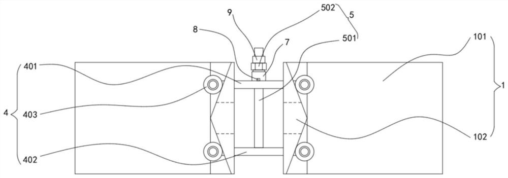
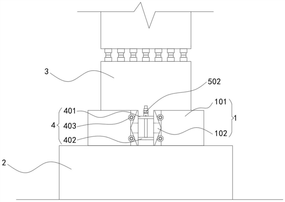
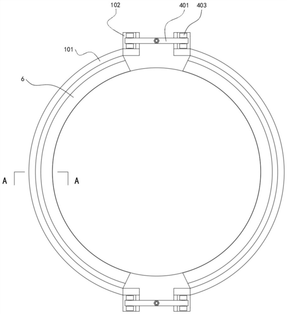
[0035] refer to Figure 1-6 , a planting pile method pile fixing device, comprising

[0036]The fixing mechanism 1 is arranged above the steel casing 2 for fixing the next pile 3. The fixing mechanism 1 includes a set of two symmetrically arranged ring-shaped steel plate fixing hoops 101, and the two ends of the ring-shaped steel plate fixing hoops 101 are Corresponding fixed limit blocks 102 are fixed respectively, and the outer side of the fixed limit blocks 102 is arranged in a straight line, and the inner side of the fixed limit blocks 102 is arranged in an isosceles triangle shape, and the upper and lower ends of the fixed limit blocks 102 Corresponding clamping grooves are respectively provided;

[0037] The locking mechanism 4 is used to lock the two...


PUM


Abstract

The invention relates to a pile splicing fixing device adopting a pile planting method. The pile splicing fixing device adopting the pile planting method comprises a fixing mechanism, a locking mechanism, a tensioning mechanism and an anti-skid clamping mechanism, wherein the fixing mechanism is arranged above a steel casing and used for fixing a next section of pile, and the fixing mechanism comprises a set of two symmetrically-arranged annular steel plate fixing hoops; the locking mechanism is used for locking the two ends of the two annular steel plate fixing hoops, and the locking mechanism comprises an upper fixing rod and a lower fixing rod which are arranged according to the height; the tensioning mechanism is used for adjusting the relative distance between the upper fixing rod andthe lower fixing rod; and the anti-skid clamping mechanism is used for clamping a pile body of the next section of pile. According to the pile splicing fixing device adopting the pile planting method, locking installation can be effectively and conveniently conducted, locking can be conducted in place at a time, downward turning deformation of anti-skid rubber materials can be effectively prevented, the proper locking stroke of the annular steel plate fixing hoops can be effectively controlled, and therefore the anti-sinking effect of a prefabricated pipe pile is effectively and greatly improved, and the service life of the device is prolonged.

Description

technical field [0001] The invention relates to a pile-connecting and fixing device of the planting pile method, which is mainly used for preventing the sinking of the pipe pile caused by the self-weight of the pipe pile or the influence of external force during the pile-connecting process. Background technique [0002] In recent years, with the rapid development of coastal buildings, foundations such as corrosive and soft soils have become more common, and building construction has increasingly high requirements for the construction quality of pile foundations. In order to improve the durability of pile foundations on corrosive foundations and prevent the damage of uplift and displacement caused by pile driving in soft soil areas to adjacent buildings and underground pipelines, pile foundation construction has gradually appeared in people's field of vision. [0003] When constructing the pile method, first drill a certain hole diameter and hole depth according to the design...

Claims


Application Information

Patent Timeline
Patent Type & Authority Applications(China)
IPC IPC(8): E02D7/00
CPCE02D7/00
Inventor 陈景镇蓝明红林凤英蒋晨王源兴刘华长胡耀祖兰明扬陈志钊刘月霞
Owner 中建四局建设发展有限公司
Why Eureka
Try Eureka