RFID Key Rotation System

a key rotation and key technology, applied in the field of radio frequency identification (rfid) applications, can solve the problems of many non-integrated applications, unnecessary complexity, and limited computer applications, and achieve the effect of reducing and increasing the complexity of the system

Active Publication Date: 2008-12-11
ORACLE INT CORP
View PDF19 Cites 9 Cited by
  • Summary
  • Abstract
  • Description
  • Claims
  • Application Information

AI Technical Summary

Benefits of technology

[0015]In some embodiments, a policy is received specifying creation of one or more external identifiers for the tag. Generating the second external identifier may include generating the second external identifier based on the policy. A rotation scheme may also be received indicating when to rotate an external identifier associated with the tag. In response to receiving the first external identifier, a determination may be made whether to generate an external identifier based on the rotation scheme. Generating the second external identifier may include generating the second external identifier in response to a positive determination to generate the external identifier. In some embodiments, the rotation scheme may include a rotation window.
[0016]In various embodiments, a third external identifier is generated based on one or more external identifie

Problems solved by technology

One problem with this arrangement is that these computer applications have traditionally been limited to using only the sensor data retrieved from the vendor supplied RFID readers.
This vendor lock-in leads to having too many non-integrated appl

Method used


Image

  • RFID Key Rotation System
  • RFID Key Rotation System
  • RFID Key Rotation System

Examples


Embodiment Construction

[0030]Embodiments of the present invention generally relate to sensor technologies and more specifically to techniques for virtualization and quality of sensor data. In order to better understand the present invention, aspects of the environment within which the invention operates will first be described.

[0031]In order to better understand the present invention, aspects of the environment within which various embodiments operate will first be described.

Collection of Sensor Data

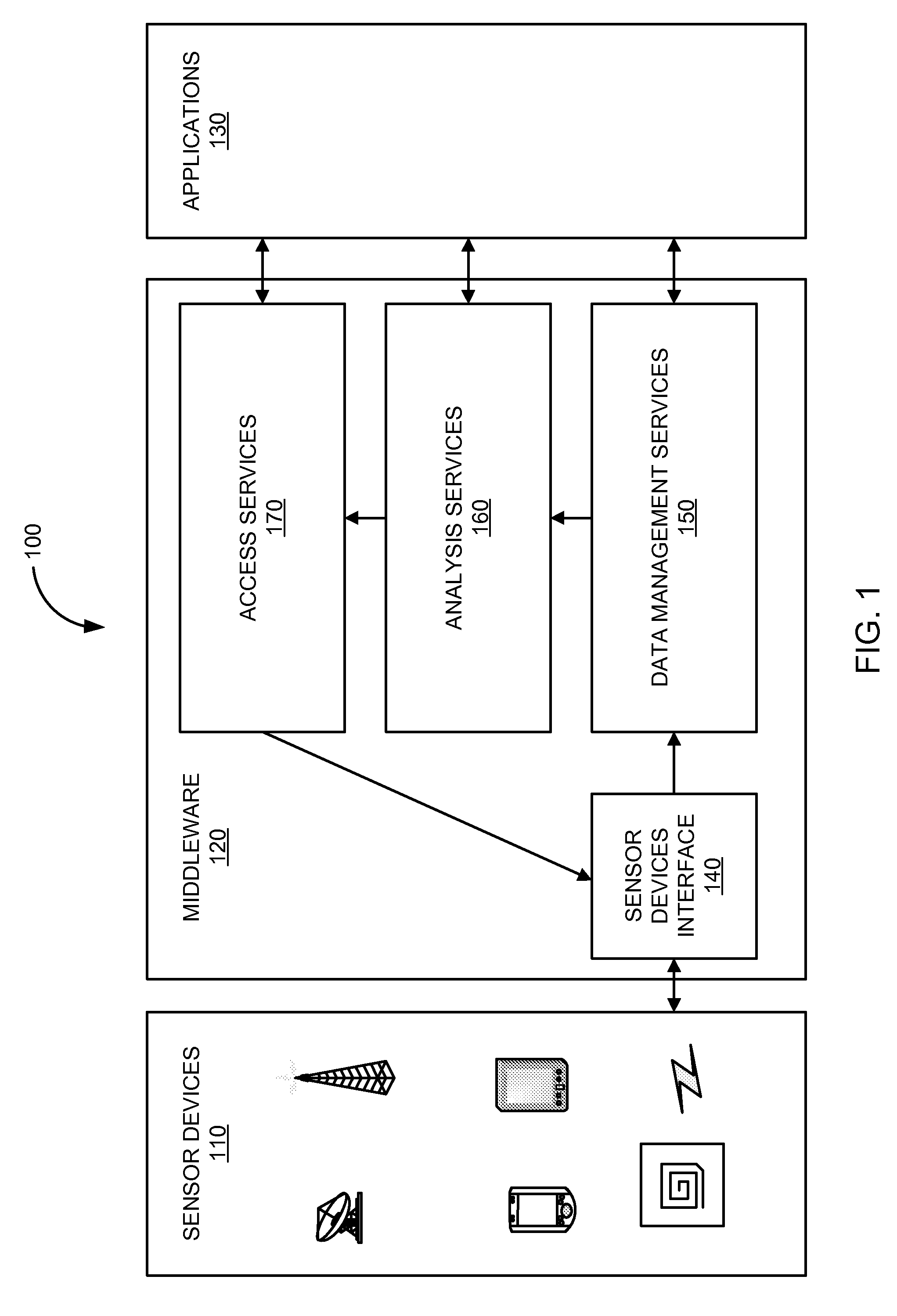
[0032]In various embodiments, methods and systems for collection of sensor data that may incorporate embodiments of the present invention augment enterprise software with RFID and sensor technologies. The methods and systems generally provides a faster reasons loop, greater visibility, an extensible framework, and scalability for the collection of sensor data from a variety of sensor devices and the processing of sensor data by a variety of applications. The systems typically can be deployed in locations where...


PUM


Abstract

In various embodiments, a method for tracking objects includes receiving an internal identifier associated with an object. A first key or external identifier for a tag is associated with the internal identifier. A second external identifier is generated and the second external identifier is then written to the tag. The second external identifier is associated with the internal identifier associated with the object.

Description

CROSS-REFERENCES TO RELATED APPLICATIONS[0001]The present disclosure may be related to the following commonly assigned applications / patents:[0002]This application is related to co-pending U.S. patent application Ser. No. 11 / 685,655 filed Mar. 13, 2007 and entitled “Virtualization and Quality of Data;”[0003]This application is related to co-pending U.S. patent application Ser. No. 11 / 685,673 filed Mar. 13, 2007 and entitled “Real-Time and Offline Location Tracking Using Passive RFID Technologies;” and[0004]This application is related to co-pending U.S. patent application Ser. No. ______ (Attorney Docket No. 021756-029100US), filed ______ and entitled “RFID and Sensor Signing System;”[0005]The respective disclosures of these applications / patents are incorporated herein by reference in their entirety for all purposes.BACKGROUND OF THE INVENTION[0006]Embodiments of the present invention generally relate to Radio Frequency Identification (RFID) applications. More specifically, embodiment...

Claims


Application Information

Patent Timeline
IPC IPC(8): G06F19/00
CPCG06Q10/06G06Q10/08
Inventor REHMAN, SAMUELSON
Owner ORACLE INT CORP
Why Eureka
Try Eureka