Clip for wireless devices

Inactive Publication Date: 2008-12-11
LIN PI FEN
View PDF13 Cites 9 Cited by
  • Summary
  • Abstract
  • Description
  • Claims
  • Application Information

AI Technical Summary

Benefits of technology

[0006]One particular aspect of the present invention is to provide a clip for wireless devices. The clip is used for receiving and hanging the wireless device (such as a cel

Problems solved by technology

Because there is no handy receiving device for the user to hang onto and take off from the

Method used


Image

  • Clip for wireless devices
  • Clip for wireless devices
  • Clip for wireless devices

Examples


Example

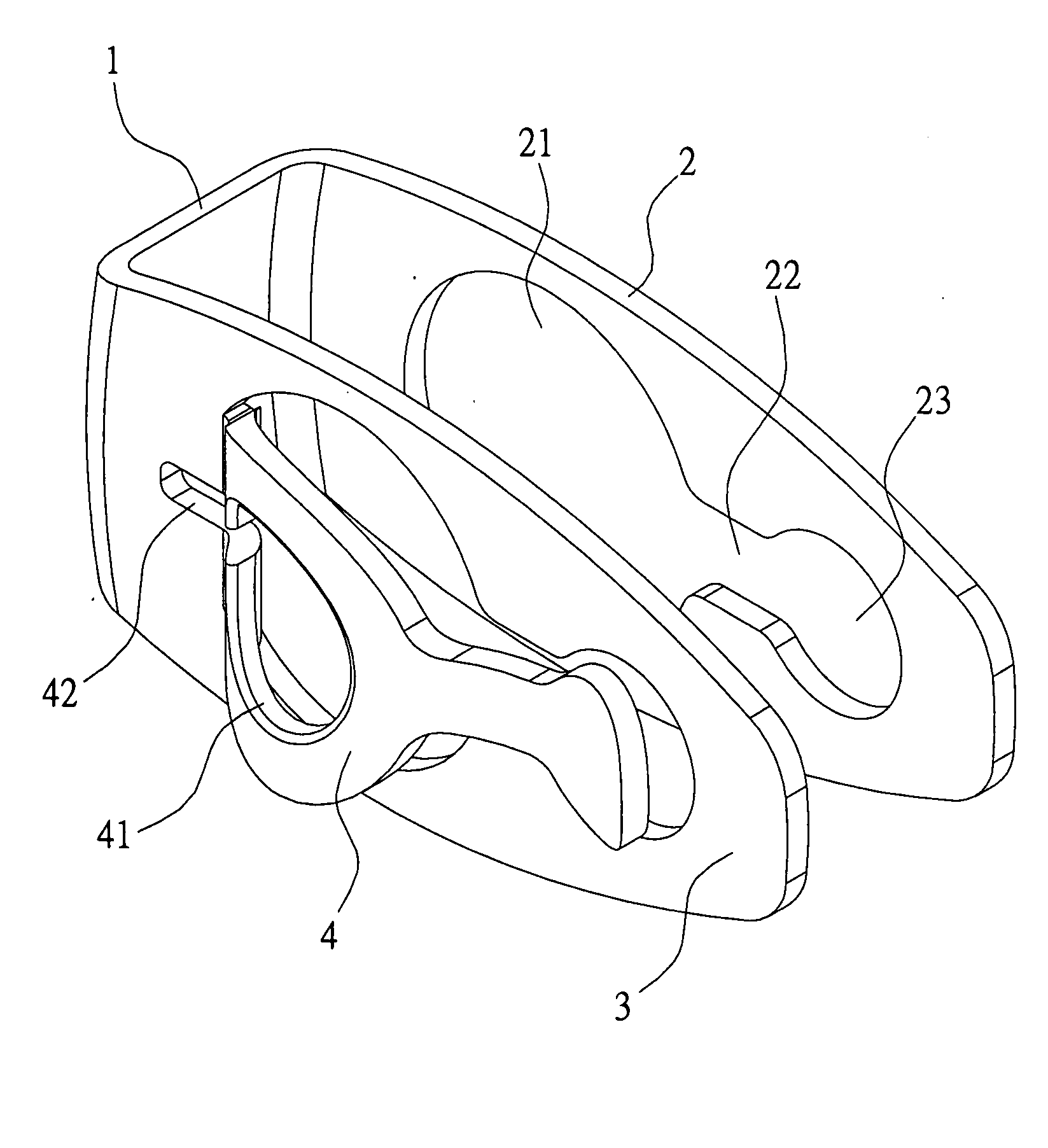
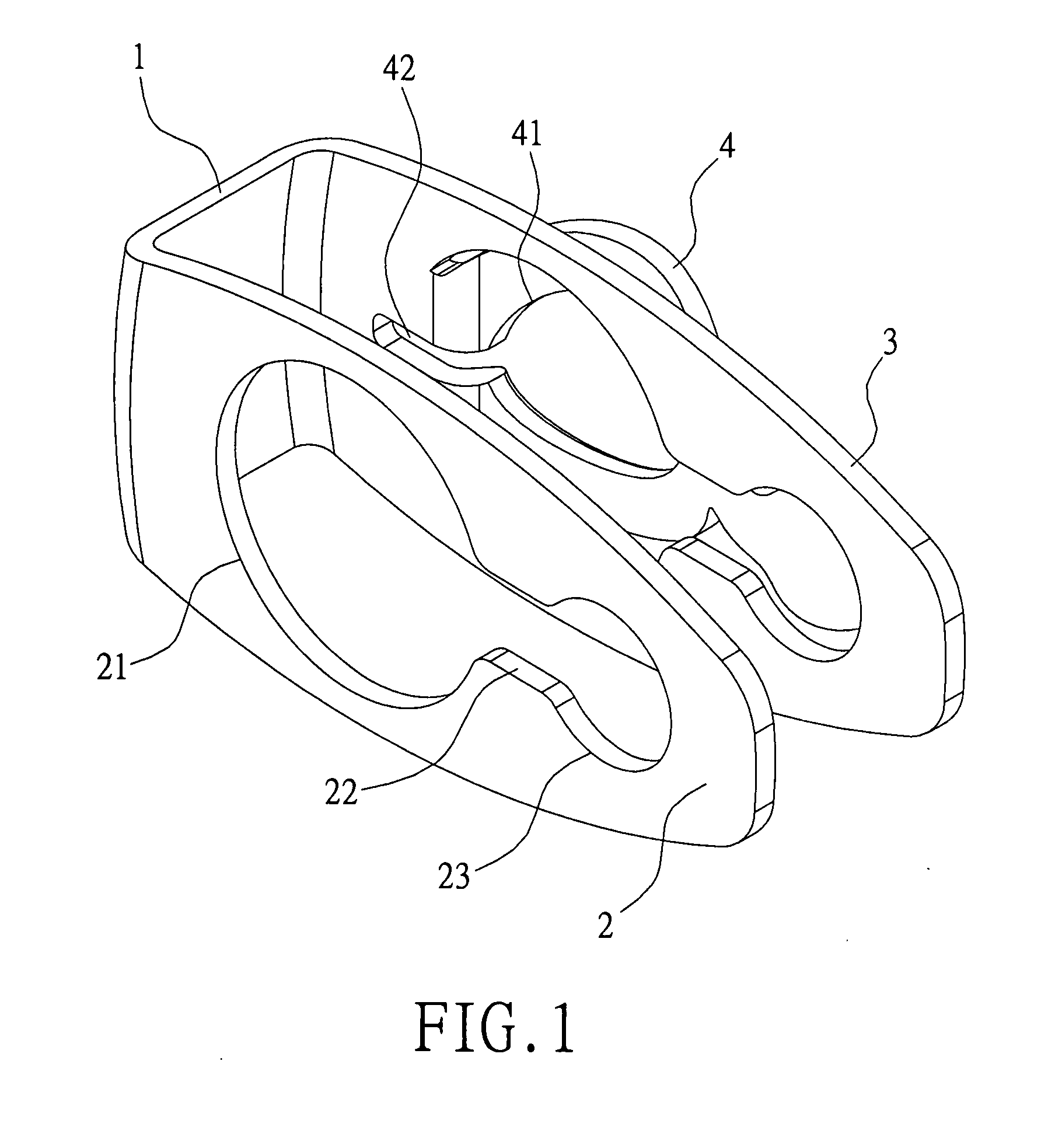
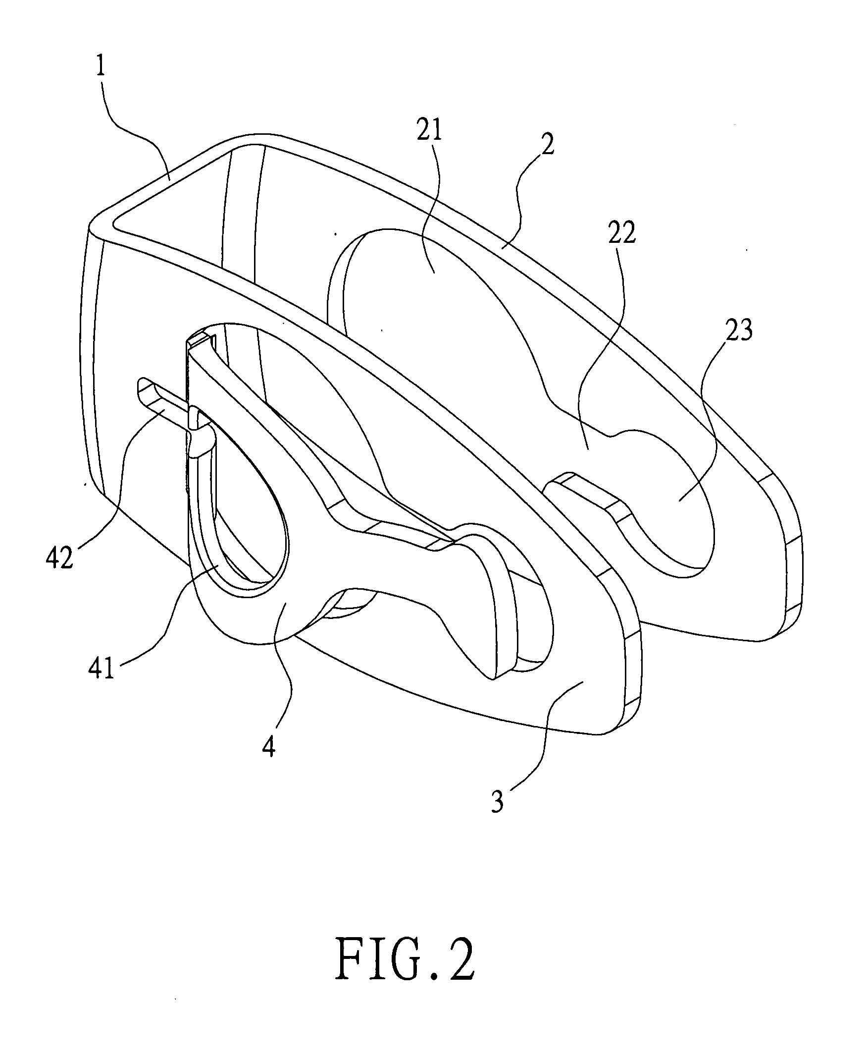
[0016]Reference is made to FIGS. 1 and 2. The clip for wireless devices includes a connecting portion 1, a first branch arm 2, a second branch arm 3, and a clipping flake 4. The first branch arm 2 and the second branch arm 3 respectively extend from two ends of the connecting portion 1 in the same direction. The connecting portion 1, the first branch arm 2, and the second branch arm 3 form a U-shaped body.

[0017]The first branch arm 2 has a through hole 21, a guiding channel 22, and a restricting hole 23. The through hole 21 links with the restricting hole 23 via the guiding channel 22. The diameter of the through hole 21 is larger than the diameter of the restricting hole 23. The clipping flake 4 is formed on one end of the second branch arm 3 and bulges outwards. One end of the clipping flake 4 is connected with one end of the second branch arm 3 and is adjacent to the connecting portion 1. The clipping flake 4 has a connecting hole 41.

[0018]Reference is made to FIGS. 3 and 4. The ...


PUM


Abstract

A clip for wireless devices includes a first branch arm and a second branch arm. One end of the first branch arm is connected with one end of the second branch arm. The first branch arm has a through hole and a restricting hole. The second branch arm has a clipping flake. The clipping flake has a connecting hole. Thereby, the wireless device passes through the through hole and slides to the restricting hole so that the wireless device is fastened on to the first branch arm, and the wireless device can also be slid to the through hole and taken off. The wireless device is clipped to the clothes by using the clipping flake and the second branch arm or is hung on the button of clothing. The user's appearance is unaffected, and it is convenient for the user to take off or carry the wireless device.

Description

BACKGROUND OF THE INVENTION[0001]1. Field of the Invention[0002]The present invention relates to a clip for wireless devices. In particular, this invention relates to a clip for wireless devices that a user can easily take off or carry the wireless device.[0003]2. Description of the Related Art[0004]Wireless communication technology has been widely applied to portable personal communication devices. For example, a variety of wireless earphones have been developed to cooperate with cell phones. The user wears the earphones to form a connection with the cell phone. The user can transmit via wireless communication technology to receive or operate the cell phone without having to hold the cell phone.[0005]Due to the developments of the semiconductor manufacturing process and ICs, electronic devices have become smaller and lighter. Electronic devices with a small and light design do not occupy a large space. Because there is no handy receiving device for the user to hang onto and take of...

Claims


Application Information

Patent Timeline
IPC IPC(8): H04M1/00
CPCA45F5/02A45F2200/0516
Inventor LIN, PI-FEN
Owner LIN PI FEN
Why Eureka
Try Eureka