Power conversion device

Inactive Publication Date: 2013-09-05
TOYOTA IND CORP
View PDF4 Cites 0 Cited by
  • Summary
  • Abstract
  • Description
  • Claims
  • Application Information

AI Technical Summary

Benefits of technology

[0004]It is an object of the present invention to provide a power conversion device

Problems solved by technology

When a plurality of power conversion circuits are provided with a single cooling device to form a single semiconductor dev

Method used


Image

  • Power conversion device
  • Power conversion device
  • Power conversion device

Examples


Embodiment Construction

[0027]A vehicle inverter according to one embodiment of the present invention will now be described with reference to the drawings.

[0028]5

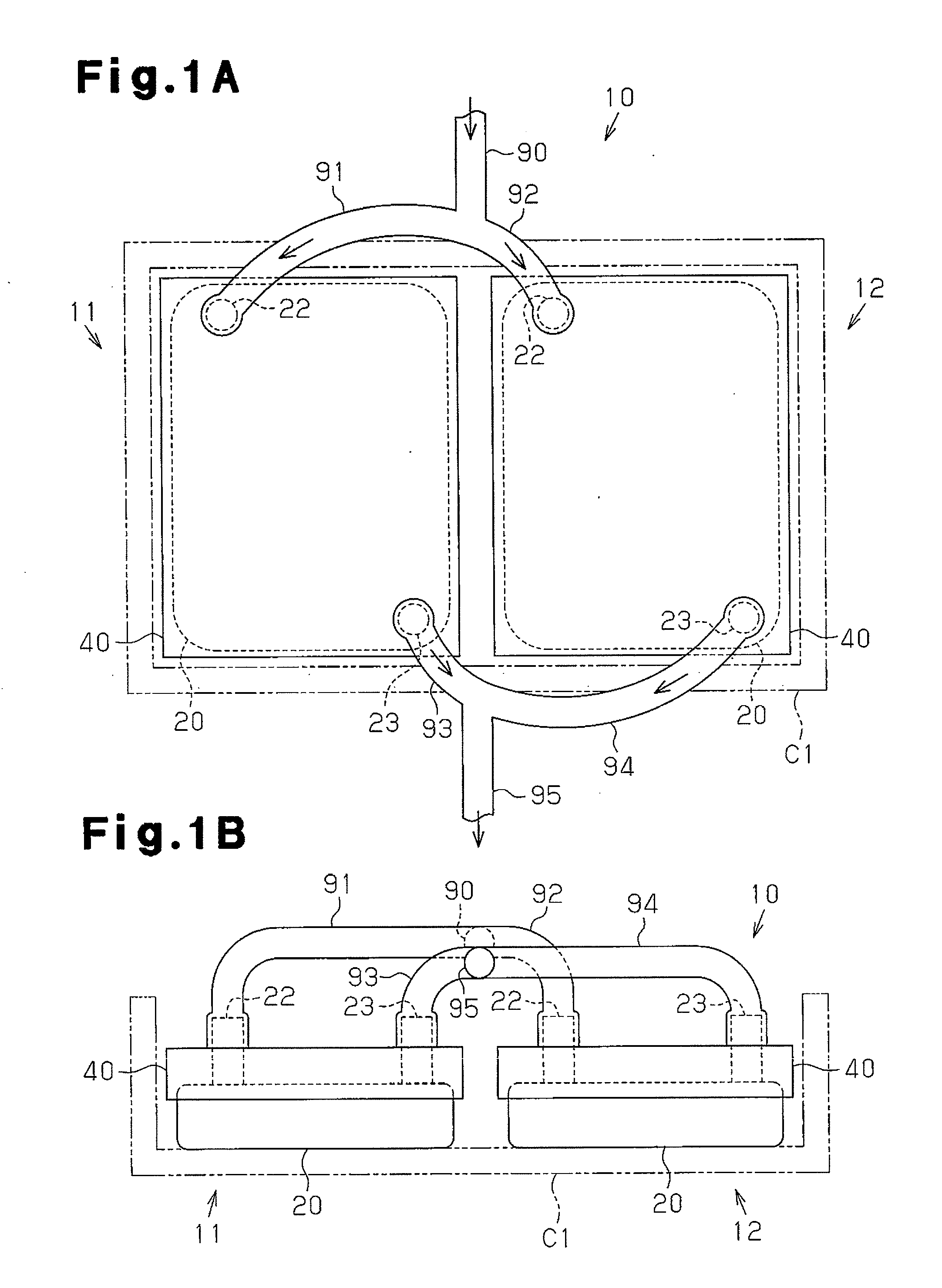
[0029]Referring to FIGS. 1A and 1B, an inverter module unit 10 includes a first inverter module 11, which serves as a first semiconductor module, a second inverter module 12, which serves as a second semiconductor module, and coolant pipes 90, 91, 92, 93, 94, and 95.

[0030]The first inverter module 11 and the second inverter module 12 have the same structure.

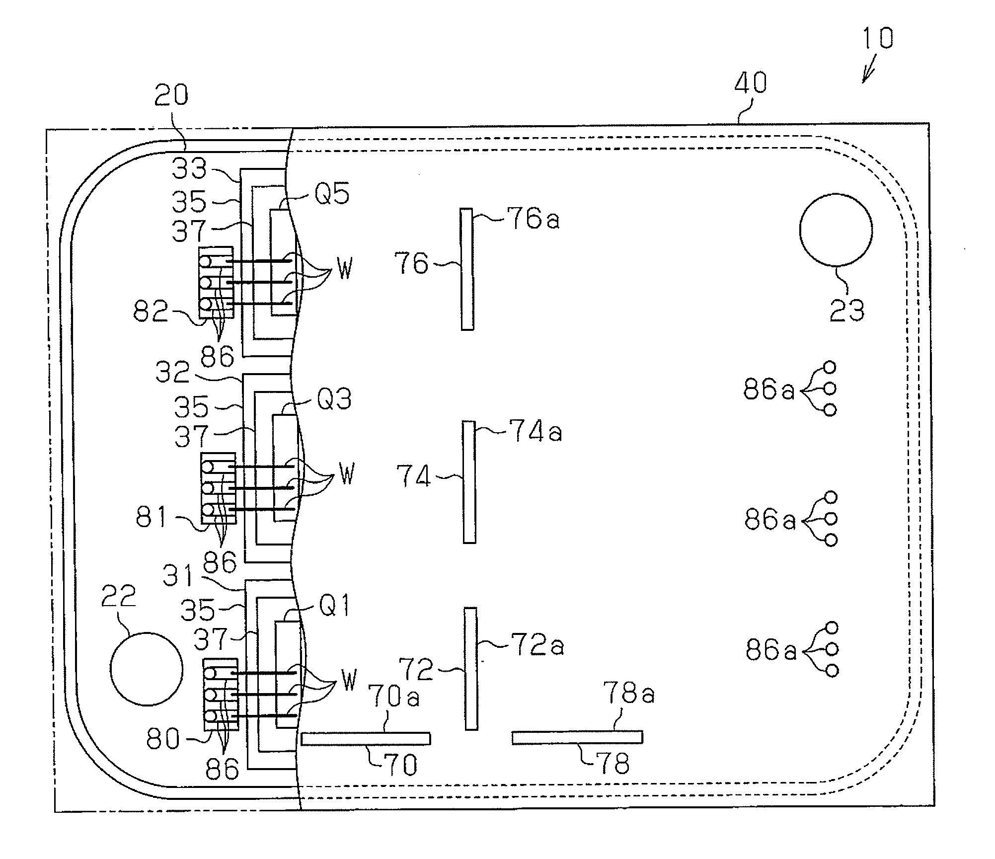
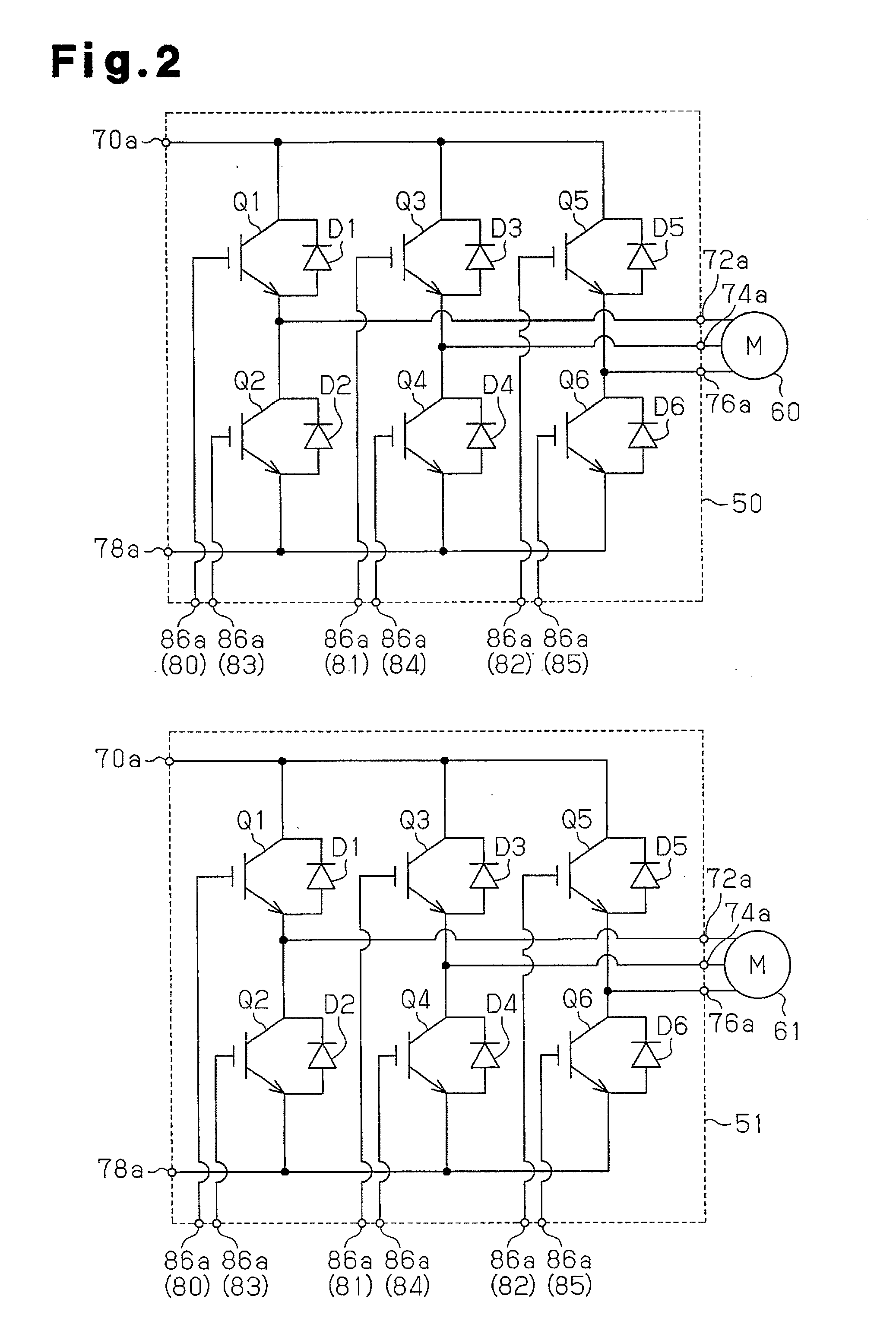
[0031]Referring to FIGS. 3A and 3B, each of the inverter modules 11 and 12 includes a cooling device. The inverter module 10 is resin-molded and includes substrates on which semiconductor elements (chips) are mounted. As shown in FIGS. 3A to 4B, each of the inverter modules 11 and 12 includes a water-cooling type cooling device 20, four insulating substrates 31, 32, 33 and 34, six transistors (chips) Q1, Q2, Q3, Q4, Q5, and Q6, six diodes (chips) D1, D2, D3, D4, D5, and D6, and a molded resin p...


PUM


Abstract

A power conversion device is provided with a plurality of semiconductor modules. Each semiconductor module includes a heat dissipation member, an insulating substrate, a semiconductor element, an external connection terminal, and a resin portion. The insulating substrate is fixed to the heat dissipation member. The semiconductor element is mounted on the insulating substrate. The external connection terminal includes a first end, which is electrically connected to the semiconductor element, and an opposite second end. The resin portion is molded to the insulating substrate, the semiconductor element, the first end, and at least part of the heat dissipation member. The semiconductor modules each form a unit.

Description

BACKGROUND OF THE INVENTION[0001]The present invention relates to a power conversion device.[0002]Japanese Laid-Open Patent Publication No. 2005-57102 discloses a semiconductor cooling unit provided with a semiconductor module, which includes a power semiconductor element, and two flat cooling tubes, each including a hollow portion through which a refrigerant flows. The semiconductor module is arranged between the two cooling tubes, which face to each other. The two cooling tubes, the semiconductor module, and a molded resin portion integrally covering the cooling tubes and the semiconductor module form a basic unit.[0003]When a plurality of power conversion circuits are provided with a single cooling device to form a single semiconductor device, component deterioration would result in the entire semiconductor device including the cooling device being defective.SUMMARY OF THE INVENTION[0004]It is an object of the present invention to provide a power conversion device that allows for...

Claims


Application Information

Patent Timeline
IPC IPC(8): H01L23/46
CPCH01L23/3735H01L23/4334H01L23/46H01L23/473H01L25/072H01L2924/13055H01L24/34H01L2224/48091H01L2224/49175H02M7/003H01L2924/00014H01L2924/15747H01L2924/15787H01L2224/45139H01L2224/40137H01L2924/181H01L2224/40225H01L24/40H01L2224/37147H01L2224/83801H01L24/37H01L2224/84801H01L24/84H01L2224/0603H01L2224/73221H01L2924/00H01L2924/00012H01L23/29
Inventor NISHI, SHINSUKEMORI, SHOGO
Owner TOYOTA IND CORP
Why Eureka
Try Eureka