
Bobbin

Inactive Publication Date: 2012-11-15
SEONG HYUNSOO +1
View PDF5 Cites 1 Cited by
  • Summary
  • Abstract
  • Description
  • Claims
  • Application Information

AI Technical Summary

Benefits of technology

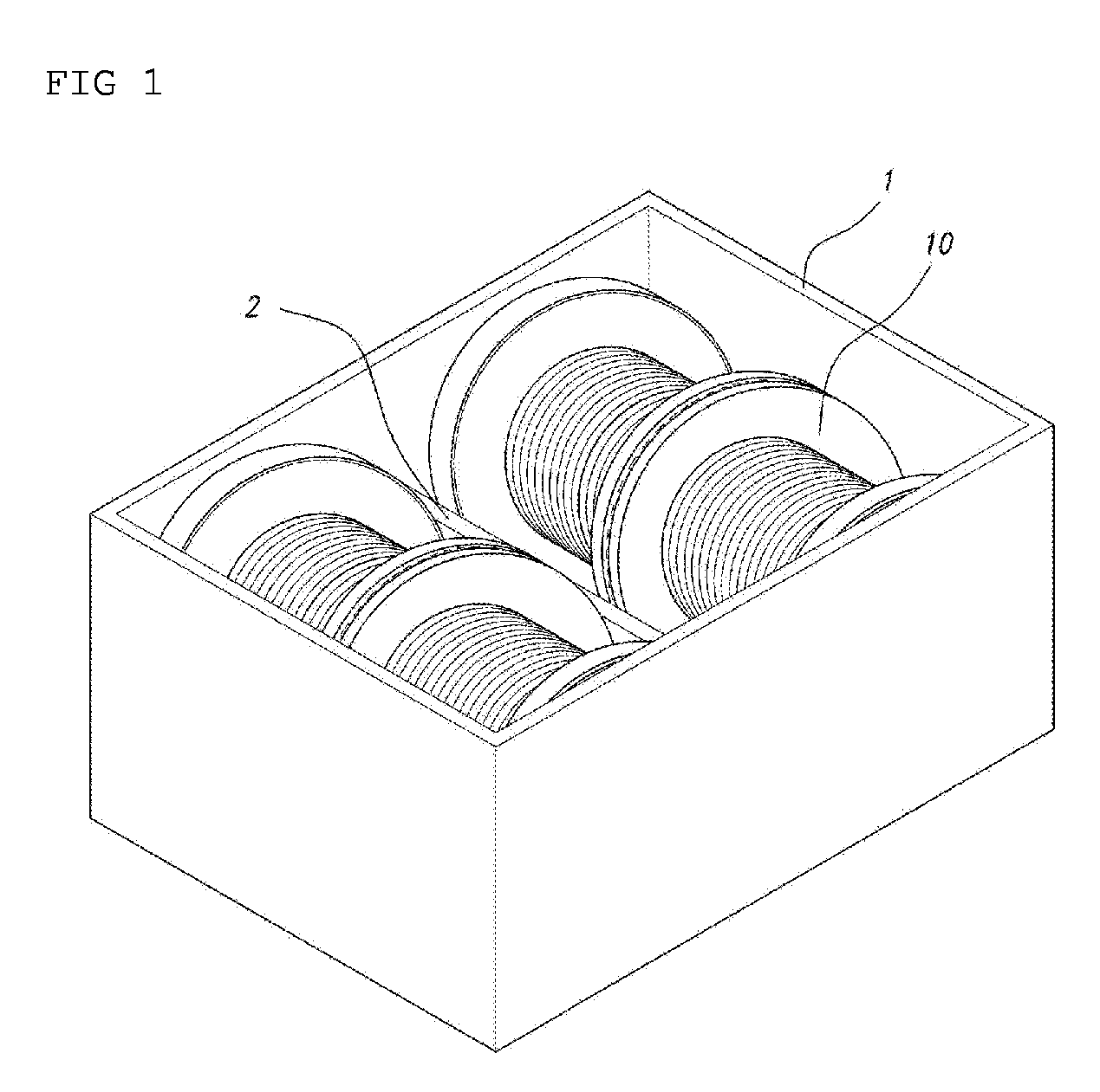
[0011]As described above, according to the present invention, a user can easily put the bobbin into the box or easily take the bobbin out of the box by using the handle part of the bobbin. In addition, even if the user puts the bobbin down on the flat surface, the bobbin can be prevented from being rolled by the first anti-rolling unit formed on the outer peripheral surface of the bobbin and the second anti-rolling unit formed on the handle part of the bobbin. Accordingly, the user can use the bobbin conveniently and safely.

Problems solved by technology

However, if heavy metallic wires such as wires for electric discharge machining are wound around the bobbins, each bobbin may have the weight of at least several tens kilograms.
In this case, the user cannot easily lift each bobbin.
In addition, the user may have a significant difficulty when lifting the bobbin by putting the hand between a box wall and each bobbin.
In this case, since the bobbin has a cylindrical shape and a heavy weight, the bobbin may be rolled, causing injury to the foot of the user.

Method used


Image

  • Bobbin
  • Bobbin
  • Bobbin

Examples


Embodiment Construction

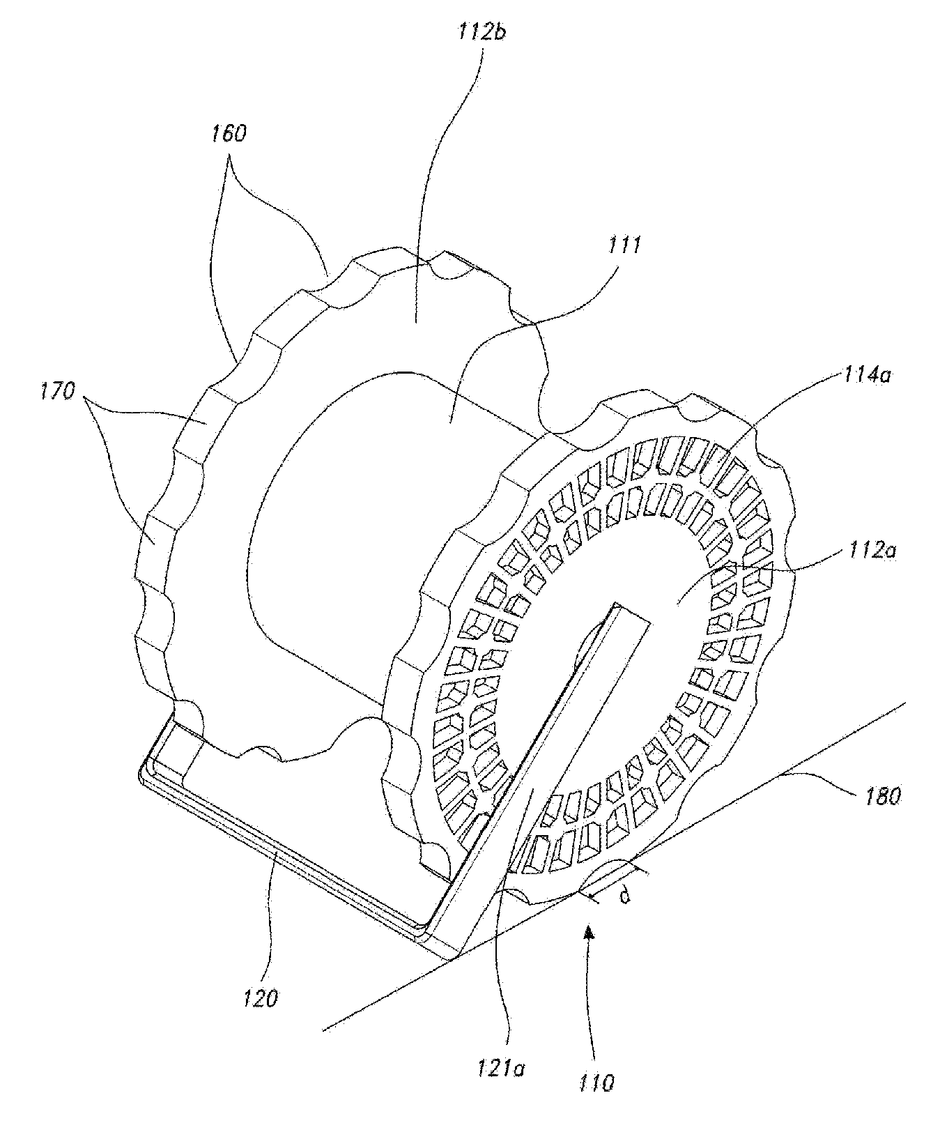
[0018]As shown in FIG. 3, a bobbin 110 according to the present invention includes a cylindrical part 111, around which a wire is wound, wing parts 112a and 112b formed both sides of the cylindrical part 111, and a through hole 113 formed at the central portion of the bobbin 110. A handle 120 is held by a user hand, and integrally formed with two support rods vertically extending from the handle 120, which include a right support rod 121a and a left support rod 121b, thereby forming a substantially “” shape. The two support rods are provided at the inner surfaces thereof with support shafts 122a and 122b inserted into the through hole 130 and with anti-rotation protrusions 115a and 115b of the handle 120 fitted into grooves 114a and 114b formed on outer surfaces of the wing parts 112a and 112b, respectively.

[0019]Therefore, after spreading the right and left support rods 121a and 121b of the handle 120 including an elastic member including plastic, the support shafts 122a and 122b a...


PUM


Abstract

Disclosed is a bobbin. The bobbin includes an anti-rolling unit capable of supporting the bobbin to prevent the bobbin from rolling on a floor. The bobbin includes a cylindrical part (111) around which a wire is wound, wing parts (112a and 112b) provided at left and right sides of the cylindrical part, having diameters greater than a diameter of the cylindrical part, and having a plate shape, a through hole (113) defined through a central portion of the cylindrical part and central portions of the left and right wing parts, a handle part (120) having a substantially “” shape and including a pair of support shafts (122a and 122b), which protrude so as to be fitted into the through hole from left and right wing parts, and left and right support rods (121a and 121b) having end portions fixed to the support shafts, respectively, and extending in parallel to the left and right wing parts while making contact with outer surfaces of the right and left wing parts, and an anti-rolling unit for the bobbin. The anti-rolling unit includes a first anti-rolling unit having a plurality of first and second regions alternately formed on outer peripheral surfaces of the wing parts having the plate shape, in which two adjacent first regions (160) or two adjacent second regions (170) make contact with a flat surface, and a second anti-rolling unit defined as the handle makes contact with the flat surface.

Description

TECHNICAL FIELD[0001]The present invention relates to a bobbin. More particularly, the present invention relates to a bobbin structure including an anti-rolling unit capable of supporting the bobbin to prevent the bobbin from rolling on a floor.BACKGROUND ART[0002]The bobbin has been used for a long time to store a fiber, a wire or the like by winding the fiber, the wire, or the like around the bobbin. In addition to light objects such as fiber, heavy objects such as metallic wires may be wound around the bobbin. Accordingly, if the metallic wire is wound around the bobbin, the whole weight of the bobbin may be significantly increased.[0003]The bobbin includes a cylindrical part, around which a wire is wound, and a wing part that has a diameter greater than that of the cylindrical part to prevent the wound wire from getting out of both sides of the cylindrical part. In other words, the wire is wound around the cylindrical part, and prevented from getting out of the cylindrical part ...

Claims


Application Information

Patent Timeline
IPC IPC(8): B65H75/18B65H75/14
CPCB65H49/38B65H2701/535B65H75/14B65H75/00B65H75/34
Inventor SEONG, HYUNSOOSEONG, HYUN-GUK
Owner SEONG HYUNSOO
Learn More