
Hanger of Overhead Projector

a projector and overhead technology, applied in the direction of rod connections, curtain suspension devices, fastening means, etc., can solve the problems of inconvenient installation of conventional hangers, inconvenient use, and need to be improved, so as to increase the convenience of installation and use

Inactive Publication Date: 2008-12-18
CHI LIN TECH CO LTD
View PDF0 Cites 14 Cited by
  • Summary
  • Abstract
  • Description
  • Claims
  • Application Information

AI Technical Summary

Benefits of technology

The present invention provides a hanger of an overhead projector that can be easily installed and adjusted. The hanger has a stepless adjustment function, making it suitable for a wider range of applications. The hanger includes a top pedestal, a suspension shaft, a rotation pedestal, a rotation pillar, a universal joint shaft, and a bottom pedestal. These components are connected together to form a hanger that can be easily adjusted in all directions. The hanger is made of one-piece structures, making it more convenient for installation and adjustment.

Problems solved by technology

Although, the method can achieve the objective of the adjustment, some problems arising on the installation and the use need to be improved.
As a result, the installation of the conventional hanger is inconvenient.
However, in such a hanger design, the adjusted altitude range is limited to the pitches of the position holes of the shaft, so that a stepless adjustment cannot be obtained, thereby being inconvenient in use.
However, in such a hanger design, the angle that can be adjusted is limited to the length of the curve hole, so that an omnidirectional angle adjustment cannot be achieved, thereby being inconvenient in use.

Method used


Image

  • Hanger of Overhead Projector
  • Hanger of Overhead Projector
  • Hanger of Overhead Projector

Examples


Embodiment Construction

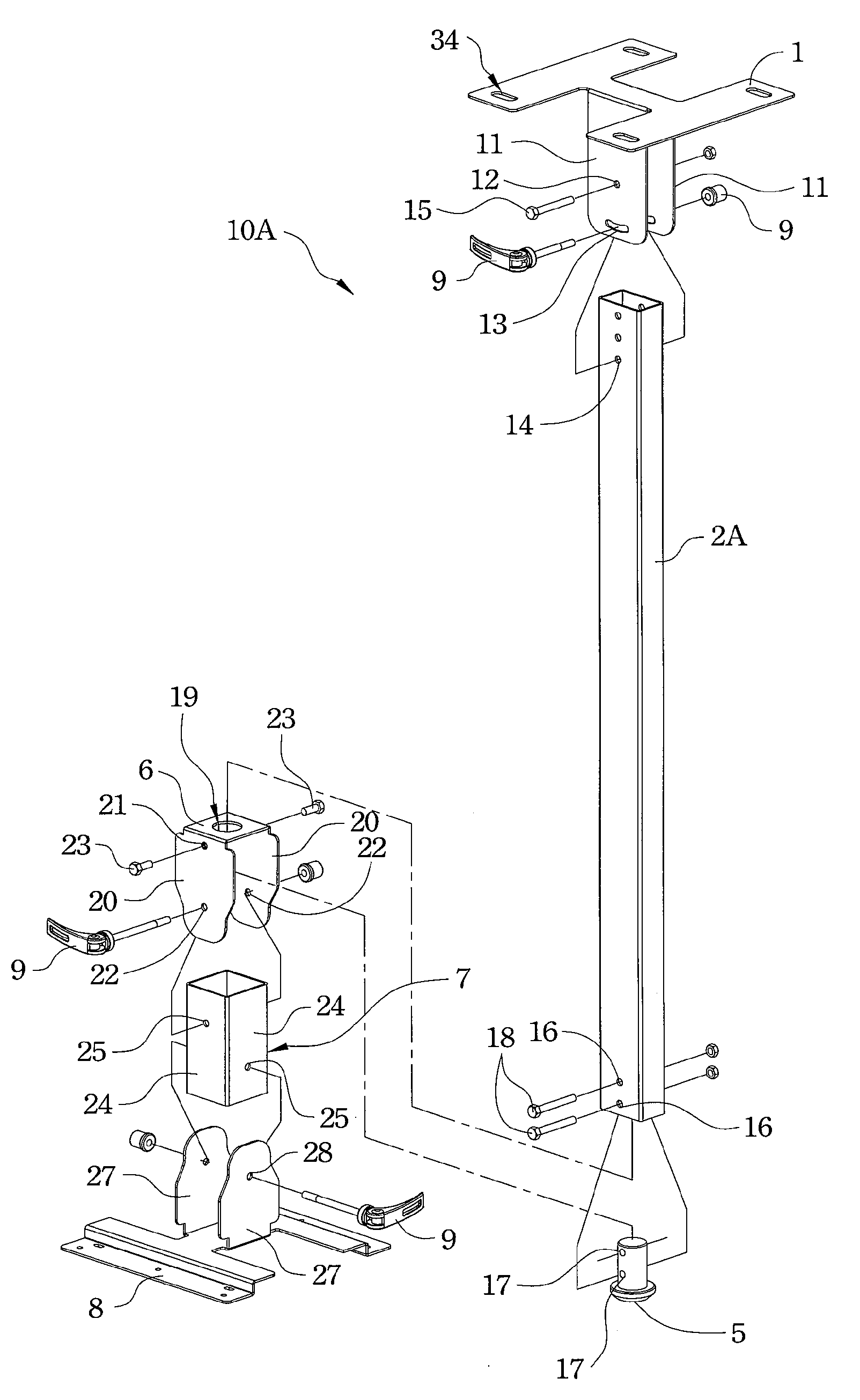
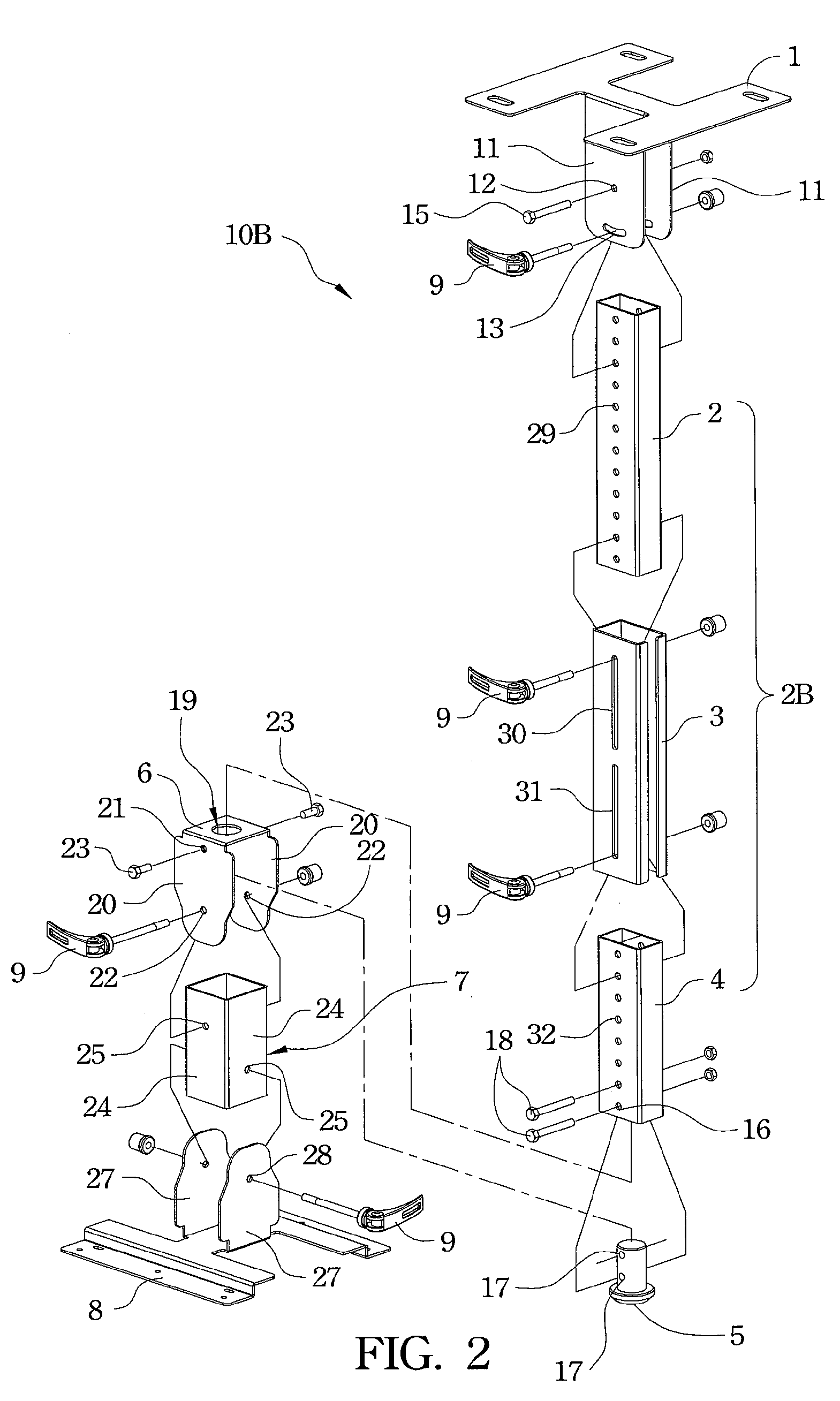
[0020]In order to improve the various disadvantages of the conventional hanger of the overhead projector, the present invention provides a hanger of an overhead projector, which is composed of a hanger structure being easily installed and adjusted. In the hanger of the present invention, quick release devices are used to replace fixing combinations each of which consists of a screw bolt and a screw nut, so that the adjusting pivots in all directions can be rapidly loosed for adjustment and can be tightened after adjustment by pulling the stem of each quick release device by bare hands.

[0021]In an exemplary embodiment, referring to FIG. 1, a hanger 10A of an overhead projector mainly comprises a top pedestal 1, a suspension shaft 2A, a rotation pillar 5, a rotation pedestal 6, a universal joint shaft 7 and a bottom pedestal 8. The top pedestal 1 can be fixed on the place where the overhead projector desires to be suspended, such as a ceiling, wherein a plurality of fixing holes pass ...


PUM


Abstract

A hanger of an overhead projector as described. The hanger comprises a top pedestal, a suspension shaft disposed between first side plates of the top pedestal, a rotation pedestal connected to a lower end of the suspension shaft, a rotation pillar set in a circular hole of the rotation pedestal and a lower end of the suspension shaft, a universal joint shaft set between side plates of the rotation pedestal, and a bottom pedestal comprising two opposite side plates, wherein a lower end of the universal joint shaft is disposed between the side plates of the bottom pedestal. In the hanger, quick release devices are used to replace conventional fixing combinations each of which consists of a screw bolt and a screw nut to fix the top pedestal and the suspension shaft, the rotation pillar and the universal joint shaft, and the universal joint shaft and the bottom pedestal.

Description

RELATED APPLICATIONS[0001]This application claims the priority benefit of U.S. Provisional Application Ser. No. 60 / 944,112, filed Jun. 15, 2007, which is herein incorporated by reference.FIELD OF THE INVENTION[0002]The present invention relates to a hanger, and more particularly, to a hanger of an overhead projector.BACKGROUND OF THE INVENTION[0003]In addition to providing a basic connection function to hang an overhead projector on a ceiling, a conventional hanger of the overhead projector further provides a multidirectional adjustment function to facilitate the adjustment of the image, so as to make the overhead projector accurately project on a screen. In the conventional hanger of the overhead projector, each of the adjustment elements of all directions in the conventional hanger mainly consists of a screw bolt and a screw nut. The adjustment is processed under the screw bolt is used as the pivot and the combination of the screw bolt and the screw nut is loosed, and after the co...

Claims


Application Information

Patent Timeline
Patent Type & Authority Applications(United States)
IPC IPC(8): F16B7/10
CPCF16B7/105
Inventor WEI, HAO-CHANCHAN, MING-JEN
Owner CHI LIN TECH CO LTD
Learn More