Vacuum cleaner

A vacuum cleaner, vacuum cleaner technology, applied in the direction of vacuum cleaners, household appliances, cleaning equipment, etc., to achieve the effects of easy installation, preventing vibration, and eliminating trouble

Inactive Publication Date: 2008-07-30
LG ELECTRONICS INC
View PDF0 Cites 10 Cited by
  • Summary
  • Abstract
  • Description
  • Claims
  • Application Information

AI Technical Summary

Problems solved by technology

Therefore, the conventional vacuum cleaner has the disadvantage that the user has to empty the dust collector body to maintain the dust collection efficiency because the dust occupies too much space in the dust collector body for its weight.

Method used


Image

  • Vacuum cleaner
  • Vacuum cleaner
  • Vacuum cleaner

Examples


Embodiment Construction

[0044] Reference will now be made in detail below to embodiments of the present invention with reference to the accompanying drawings.

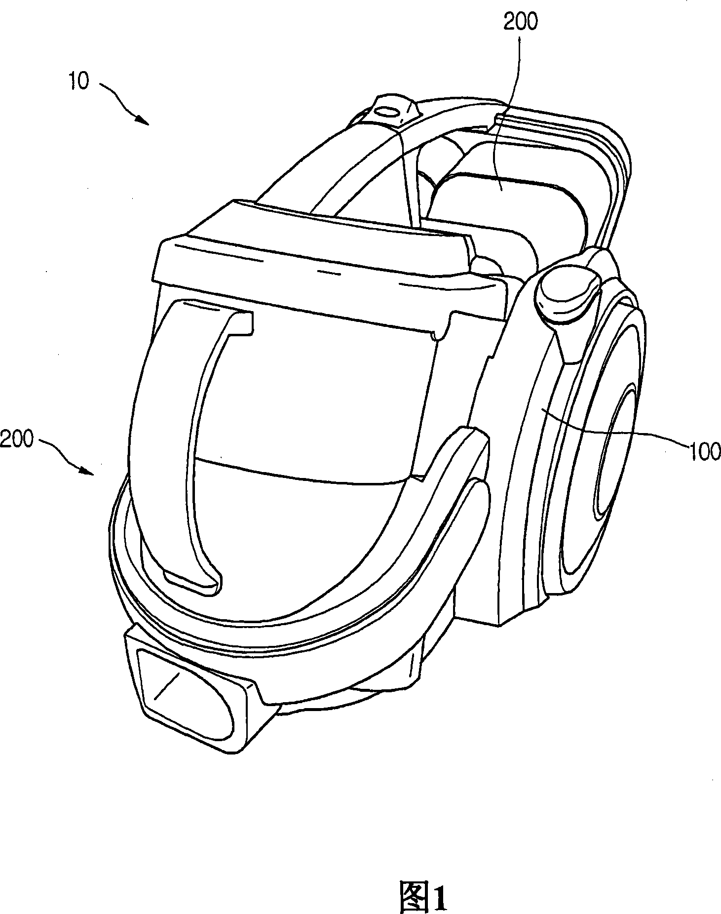
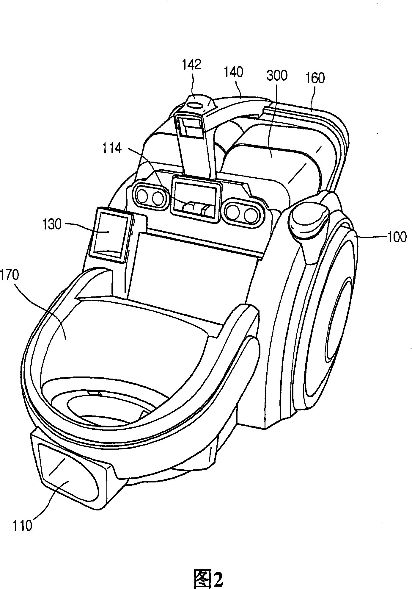
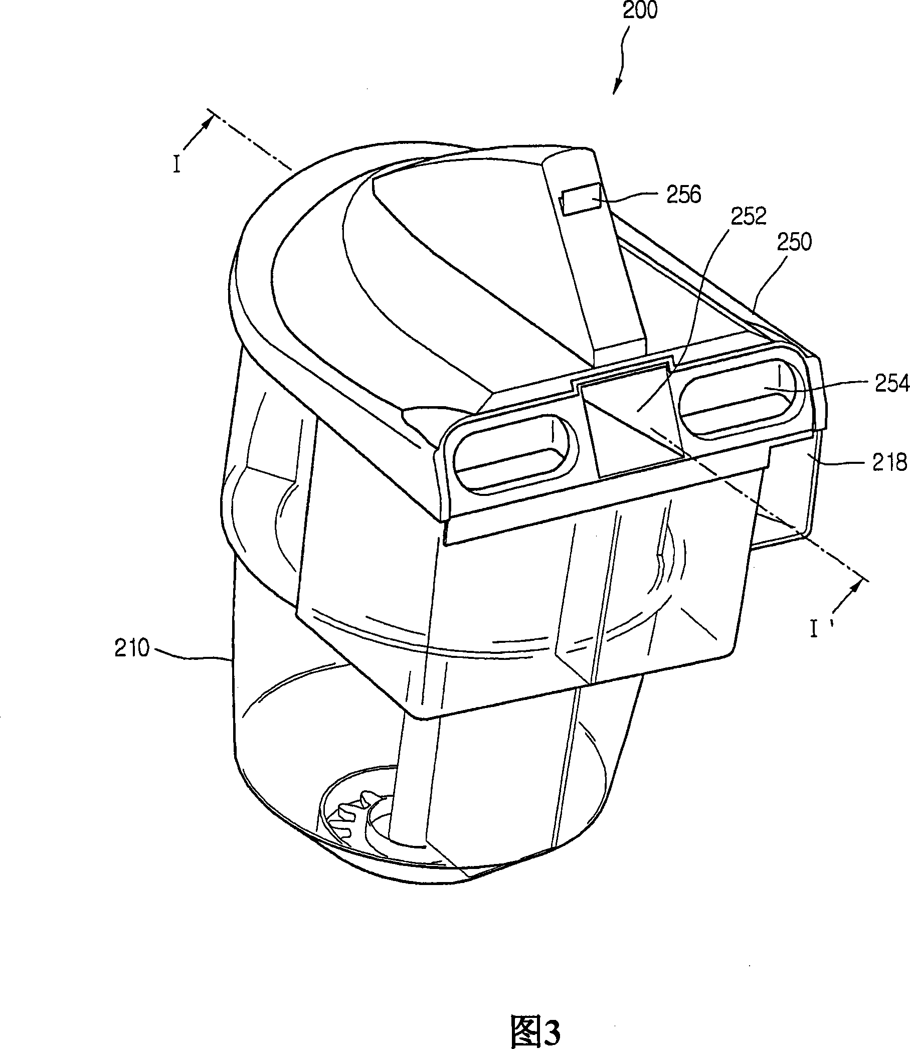
[0045] 1 is a perspective view of a vacuum cleaner according to a preferred embodiment of the present invention, FIG. 2 is a perspective view showing a state in which a dust collector is separated from the vacuum cleaner, and FIG. 3 is a perspective view of a dust collector according to a preferred embodiment of the present invention. picture.

[0046] Referring to FIGS. 1 to 3, a vacuum cleaner 10 according to the present invention includes: a cleaner body 100 having a suction motor (not shown) that generates suction power inside; Dust included.

[0047] Further, although not shown, a suction nozzle sucking air containing dust and a connection pipe connecting the suction nozzle to the cleaner main body 100 are included.

[0048] Because it is the same as the prior art, the detailed description of the basic composition of the suction nozzle...


PUM


Abstract

The disclosure relates to a vacuum cleaner comprising: a cleaner body having a dust collector mount formed therein; a dust collector connected to and removable from the dust collector mount and having a dust storage therein; at least one compression a part movably arranged in the dust storage part for reducing the volume of dust stored in the dust storage part; a power transmission unit connected with the compression part for transmitting driving force to the compression part from the outside; and a control unit for determining The amount of dust stored in the dust storage unit.

Description

technical field [0001] The present invention relates to vacuum cleaners, and more particularly to vacuum cleaners which maximize the dust collection capacity of the dust collector. Background technique [0002] In general, a vacuum cleaner is a device that filters dust in a machine body after sucking air containing dust using vacuum pressure generated from a suction motor provided in the body. [0003] A conventional vacuum cleaner includes: a nozzle that sucks dusty air; a cleaner body connected to the nozzle; an extension pipe that guides air sucked through the nozzle to the cleaner body; and a connection pipe that connects air passing through the extension pipe to the cleaner body. [0004] Here, a nozzle inlet of a predetermined size is formed at the bottom of the nozzle to suck air including dust on the floor. [0005] On the other hand, a driving device generating suction power is provided inside the cleaner main body so that external air including dust is sucked thro...

Claims


Application Information

Patent Timeline
Patent Type & Authority Applications(China)
IPC IPC(8): A47L5/12
Inventor 尹昌虎河建镐金镇泳李昌勋徐真旭俞明植黄满泰梁海锡高武铉秋宗寿黄弼载
Owner LG ELECTRONICS INC
Why Eureka
Try Eureka