Device and method for replacing vibration motors

A technology of vibrating motors and moving trolleys, applied in electromechanical devices, manufacturing motor generators, lifting devices, etc., can solve the problems of increased safety risk factor, increased work-related injury rate, time waste, etc., to improve installation convenience and improve work efficiency , Easy and fast installation

Active Publication Date: 2015-11-18
唐山瑞丰钢铁(集团)有限公司
View PDF5 Cites 9 Cited by
  • Summary
  • Abstract
  • Description
  • Claims
  • Application Information

AI Technical Summary

Problems solved by technology

[0002] Vibrating screens are widely used as an indispensable equipment for screening raw and auxiliary materials in the metallurgical industry, among which vibration motors play a vital role in screening. With the continuous development of the metallurgical industry, more and more raw and auxiliary materials are screened The production line requires a short process and a compact structure between the equipment, which leads to the space limitation of some equipment during the installation and disassembly process, especially the lifting and moving during the dismantling and installation of the vibration motor are very difficult. According to the current technology Speaking of the removal and installation of the vibration motor, a reasonable lifting point is first required, the chain hoist is fixed at the lifting point, and the vibration motor is lifted by the chain hoist. However, in this process, it is necessary to find a suitable lifting point, even involving high altitude. Install the lifting point during the operation, which will waste time and increase the safety risk factor. During the lifting process, it may cause bump damage to the equipment. In addition, during the removal and installation of the vibration motor, workers are involved in carrying the vibration motor. In a narrow space The internal handling of equipment has caused great difficulties for workers, and the work efficiency is low, which increases the rate of work-related injuries

Method used


Image

  • Device and method for replacing vibration motors
  • Device and method for replacing vibration motors

Examples


specific Embodiment approach

[0031] The present invention will be further described below in conjunction with the examples, the purpose is only to better understand the contents of the present invention, therefore, the examples given do not limit the protection scope of the present invention.

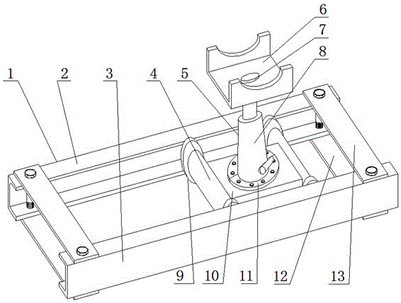
[0032] see figure 1 , including driving track 1, mobile trolley 4, lifting mechanism 5 and bracket 6, driving track 1 includes first channel steel 2 and second channel steel 3, the upper end faces of first channel steel 2 and second channel steel 3 both sides The upper baffle 13 and the lower baffle 12 are respectively fixedly connected. The upper baffle 13 is processed with two holes with a diameter of 22mm, and the lower baffle 12 is processed with two threads of M20mm corresponding to the upper baffle 13. Holes, the first channel steel 2 and the second channel steel 3 respectively correspond to the upper baffle plate 13 and the lower baffle plate 12 and are processed with a hole with a diameter of 22mm and a thr...


PUM


Abstract

The invention relates to the field of auxiliary installation equipment, and specifically relates to a device and a method for replacing vibration motors. The device comprises a mobile trolley, a running track, a lifting mechanism, and a bracket. The mobile trolley is arranged on the running track. The lifting mechanism is arranged on the mobile trolley. The bracket is arranged on the lifting mechanism. The mobile trolley moves on the running track to go out of and into a predetermined area. The lifting mechanism drives the bracket to go up and down to send the bracket to a specified installation or removal position of a vibration motor. By adopting the device and the method, equipment handling by workers is avoided, the labor intensity of workers is reduced, the safety coefficient is high, the problem that vibration motor installation and removal is vulnerable to space limitations and vibration motor transfer is difficult is overcome, and the work efficiency is improved. The device is simple in structure and easy to transport and carry, adapts to a variety of space operations, and is simple and easy to install.

Description

technical field [0001] The invention relates to auxiliary installation equipment, in particular to a device and method for replacing a vibration motor. Background technique [0002] Vibrating screens are widely used as an indispensable equipment for screening raw and auxiliary materials in the metallurgical industry, among which vibration motors play a vital role in screening. With the continuous development of the metallurgical industry, more and more raw and auxiliary materials are screened The production line requires a short process and a compact structure between the equipment, which leads to the space limitation of some equipment during the installation and disassembly process, especially the lifting and moving during the dismantling and installation of the vibration motor are very difficult. According to the current technology Speaking of the removal and installation of the vibration motor, a reasonable lifting point is first required, the chain hoist is fixed at the ...

Claims


Application Information

Patent Timeline
Patent Type & Authority Applications(China)
IPC IPC(8): H02K15/00B66F7/08
Inventor 齐超群李雪松周涛吴鹏孙仕良黄昆奕张超
Owner 唐山瑞丰钢铁(集团)有限公司
Why Eureka
Try Eureka