Heat Insulating Container

a technology of insulating containers and heat, which is applied in the direction of domestic cooling devices, lighting and heating devices, transportation and packaging, etc., can solve the problems of not producing satisfactory strength in the radial direction, and achieve excellent advantages, reduce the number of steps and materials, and heat shrinkability.

Inactive Publication Date: 2008-12-25
FUJI SEAL INTERNATIONAL INC
View PDF4 Cites 29 Cited by
  • Summary
  • Abstract
  • Description
  • Claims
  • Application Information

AI Technical Summary

Benefits of technology

[0018]As described above, according to the heat insulating container of the present invention, there is provided a container body having a bottomed tubular shape and an outer shell that is formed by a foamed resin sheet having heat shrinkability and covers a peripheral wall of the container body with a space created between the peripheral wall and the outer shell, in which the outer shell includes a tubular portion disposed opposite to the peripheral wall of the container body and an annular portion extending from an opening edge of a lower end of the tubular portion towards the inside of the tubular portion, and the annular portion has a distal end and a proximal end, in which the distal end is located farther from an inner peripheral surface of the tubular portion than the proximal end is. Whereby, it is possible to produce an excellent advantage to reduce the number of steps and materials in manufacturing as well as ensuring a satisfactory strength of the lower end side of the outer shell.

Problems solved by technology

However, when the external force has been applied, as mentioned above, the external force acts locally to an inner peripheral edge of the horizontal annular portion 152, causing buckling in the inner peripheral edge, which may lead to inward or outward buckling or breaking, of the horizontal annular portion 152, posing a problem of not producing a satisfactory strength in the radial direction in the lower end side of the outer shell 150 merely by the buckling strength of the horizontal annular portion 152.

Method used


Image

  • Heat Insulating Container
  • Heat Insulating Container
  • Heat Insulating Container

Examples


first embodiment

[0034]Now, the description will be made for the present invention with reference to the attached drawings.

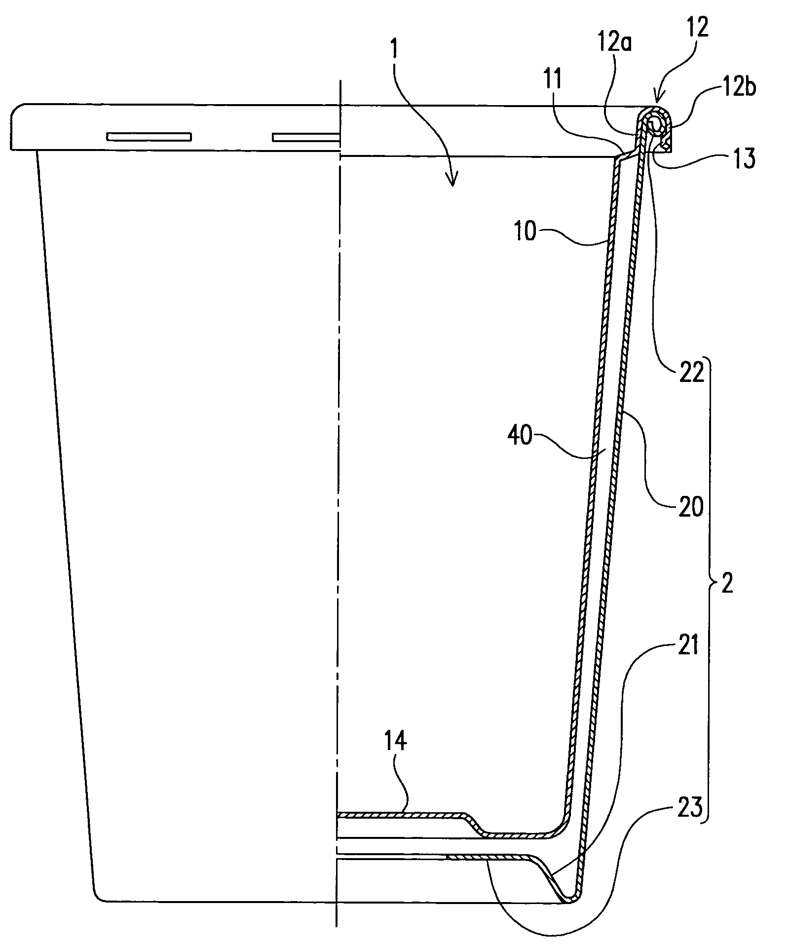
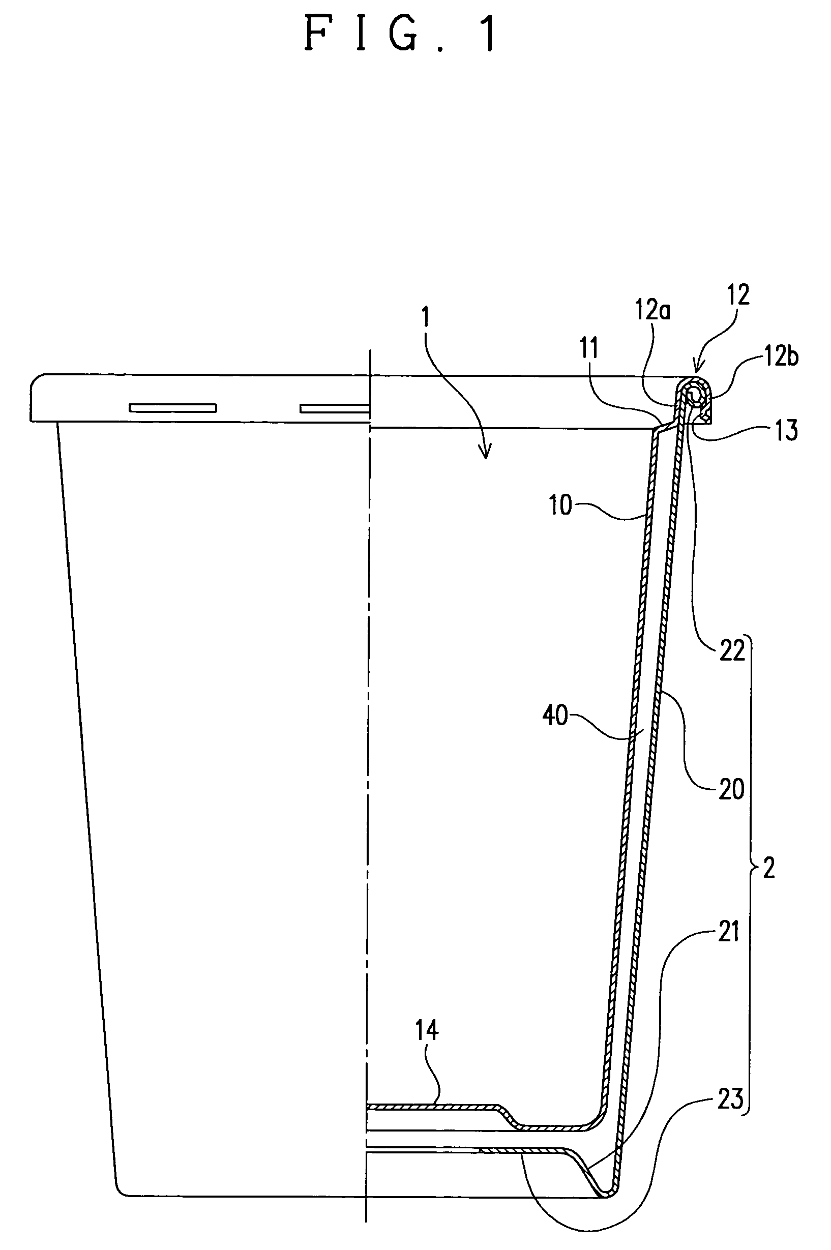
[0035]A heat insulating container of this embodiment is made up of a container body 1 having a bottomed tubular shape, and an outer shell 2 that covers a peripheral wall 10 of the container body 1, as illustrated in FIG. 1.

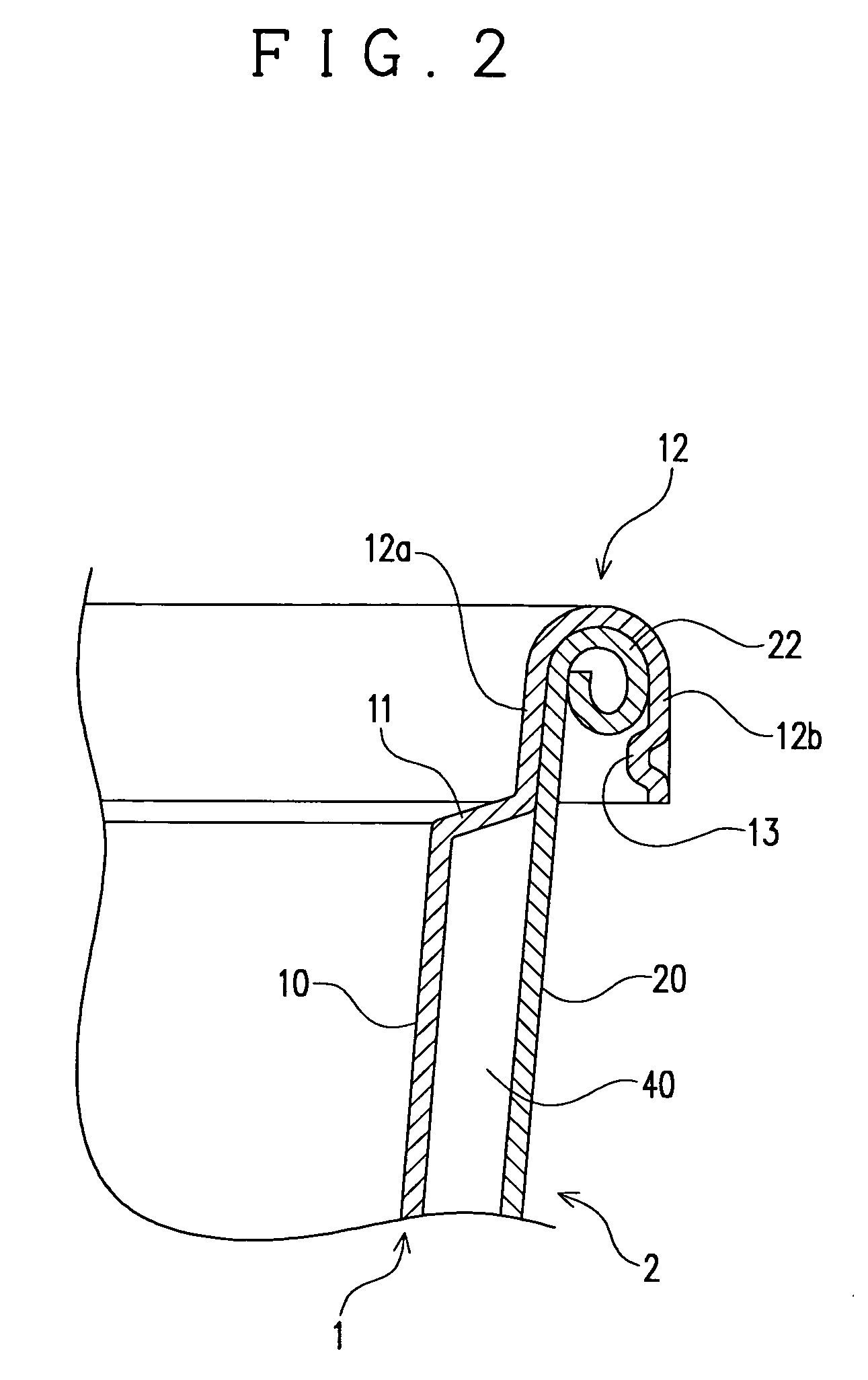
[0036]The container body 1 is a resin molded product molded by a molding technique such as injection molding, blow molding, vacuum molding or pressure molding. The container body 1 is formed into a tubular shape with the peripheral wall 10 being decreased in diameter towards the lower end. An upper end of the peripheral wall 10 of the container body 1 is provided with an annular connection portion 11 that extends outward and has an outer peripheral edge connected with a lower end of an inner peripheral piece 12a of an annular flange portion 12 having a downwardly opening U-shaped cross section.

[0037]An outer peripheral piece 12b of the flange portion 12 has pl...

second embodiment

[0103]The lower peripheral wall portion 10b has an opening edge of the upper end connected to the upper peripheral wall portion 10a via the connection portion 5, and a lower end opening closed by the bottom portion 14. The lower peripheral wall portion 10b is formed into a tubular, inverted conical shape (tubular body having an inverted truncated conical shape) with an outer diameter and an inner diameter decreasing towards the lower end. Likewise the lower tubular part 114 of the second embodiment, the lower peripheral wall portion 10b of this embodiment is made up of a thick tubular section 114a close to an upper end opening connected to the connection portion 5, and a thin tubular section 114b connected to an opening edge of a lower end of the thick tubular section 114a with taking into account the flow of a resin during molding.

[0104]Since the lower peripheral wall portion 10b is, as described above, connected to the upper peripheral wall portion 10a via the connection portion 5...


PUM


Abstract

A heat insulating container enabling a reduction in man-hour and materials in production while sufficiently securing the strength of an external body on its bottom side. The container comprises a bottomed cylindrical container body and the external body formed of a foam resin sheet with thermal shrinkage properties and covering the peripheral wall of the container body to form a space between the peripheral wall and the external body. The external body comprises a tubular part opposed to the peripheral wall of the container body and an annular part extended from the bottom opening edge part, as a base end, in the tubular part. The annular part is characterized in that the tip side thereof is apart from the inner peripheral surface of the tubular part more than the base end part side thereof.

Description

FIELD OF THE INVENTION[0001]The present invention relates to a heat insulating container that includes a container body having a bottomed tubular shape for placing therein a content such as very hot food or drink and an outer shell covering the container body with a space between the outer shell and a peripheral wall of the container body, through which heat insulating effect is produced.BACKGROUND OF THE INVENTION[0002]There have been hitherto proposed various types of heat insulating containers for placing therein instant foods or the like such as soup or noodle served by pouring boiled water, or for placing therein a separately heated drink or the like.[0003]Of them, one type of the heat insulating containers includes, as illustrated in FIG. 14, a container body 100 molded into a bottomed tubular shape, an outer shell 150 covering a peripheral wall 101 of the container body 100, in which a space 200 is created between the peripheral wall 101 of the container body 100 and the oute...

Claims


Application Information

Patent Timeline
Patent Type & Authority Applications(United States)
IPC IPC(8): B65D81/38
CPCB65D81/3869
Inventor TAKEO, KAORUSAKAI, RYUSUKE
Owner FUJI SEAL INTERNATIONAL INC
Why Eureka
Try Eureka