Surgical stapling instrument with an artculating end effector

a technology of end effector and surgical stapling, which is applied in the direction of surgical staples, surgical forceps, paper/cardboard containers, etc., can solve the problems of premature return of cutting members, difficult use of staplers, and inability to prevent the end effector from being articulated relative to the shaft assembly

Active Publication Date: 2008-12-25
CILAG GMBH INT
View PDF119 Cites 67 Cited by
  • Summary
  • Abstract
  • Description
  • Claims
  • Application Information

AI Technical Summary

Benefits of technology

[0012]In at least one form of the invention, a surgical instrument can include a shaft assembly, an end effector movable relative to the shaft assembly, and a locking mechanism configured to engage the shaft assembly and / or the end effector in order to fix, or lock, the relative relationship between the shaft assembly and the end effector. In various embodiments, the end effector can include an anvil and a channel where the channel can be configured to receive a staple cartridge and the anvil can be movably coupled to the channel. In at least one embodiment, the surgical instrument can further include a closure system configured to generate a closing motion where the anvil can be responsive to the closing motion. In various embodiments, the closure system can be further configured to engage the locking mechanism and prevent the locking mechanism from unlocking the relative relationship between the shaft assembly and the end effector.

Problems solved by technology

These closing systems, however, do not prevent the end effector from being articulated relative to the shaft assembly after the jaw members have been closed.
If a surgeon is unsatisfied with the position of the end effector, however, the surgeon must typically activate a release mechanism on the surgical stapler to pivot the anvil into an open position and then reposition the end effector.
Such staplers, however, are often difficult to use as the force required to extend the return spring as the cutting member is advanced is often significant.
Furthermore, such return springs often apply a biasing force to the cutting member as it is advanced which can, in various circumstances, prematurely return the cutting member, especially in embodiments where multiple strokes of a trigger are required to completely advance the cutting member.

Method used


Image

  • Surgical stapling instrument with an artculating end effector
  • Surgical stapling instrument with an artculating end effector
  • Surgical stapling instrument with an artculating end effector

Examples


Embodiment Construction

[0084]Certain exemplary embodiments will now be described to provide an overall understanding of the principles of the structure, function, manufacture, and use of the devices and methods disclosed herein. One or more examples of these embodiments are illustrated in the accompanying drawings. Those of ordinary skill in the art will understand that the devices and methods specifically described herein and illustrated in the accompanying drawings are non-limiting exemplary embodiments and that the scope of the various embodiments of the present invention is defined solely by the claims. The features illustrated or described in connection with one exemplary embodiment may be combined with the features of other embodiments. Such modifications and variations are intended to be included within the scope of the present invention.

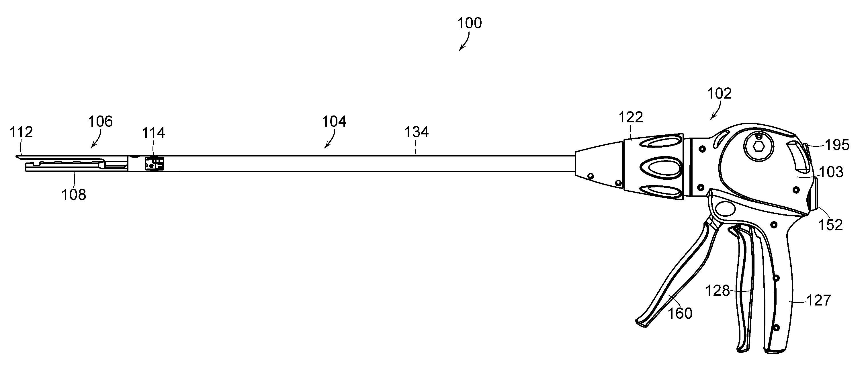
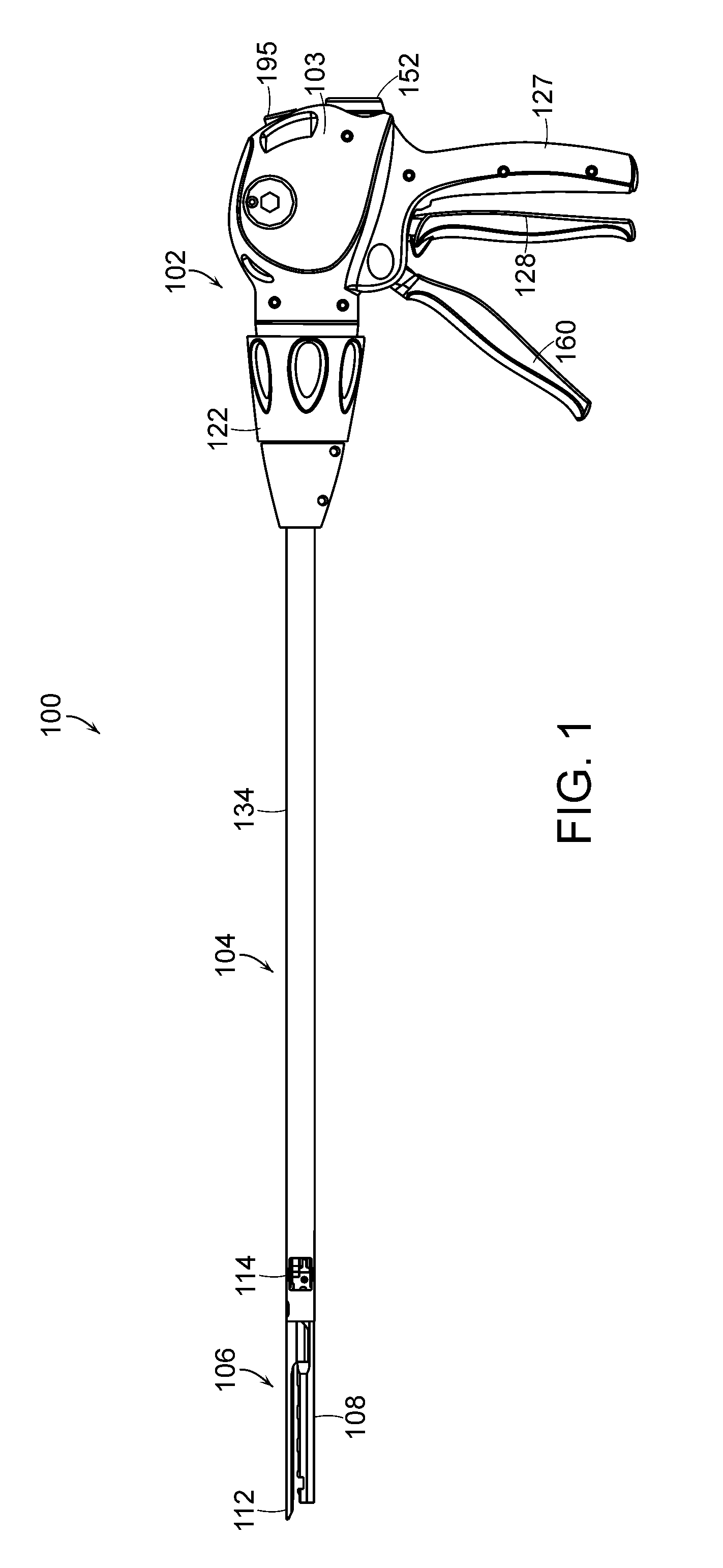
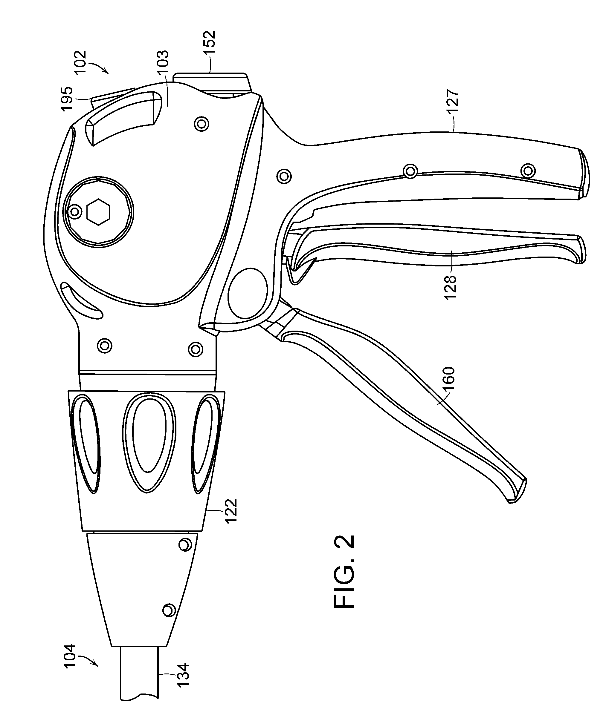
[0085]In various embodiments, a surgical instrument in accordance with the present invention can be configured to insert surgical staples into soft tissue, for exa...


PUM

PropertyMeasurementUnit
perimeteraaaaaaaaaa
relative movementaaaaaaaaaa
soft tissueaaaaaaaaaa

Abstract

A surgical instrument including a shaft assembly and an end effector, where the end effector can be moved relative to the shaft assembly. The shaft assembly can include a lock member selectively engageable with the end effector to limit, or prevent, relative movement therebetween. In at least one embodiment, the end effector can include a lock member having a plurality of teeth and/or a plurality of recesses, where the shaft assembly lock member can engage the teeth and/or recesses to fix the relative position between the end effector and shaft assembly. In various embodiments, the teeth can be positioned between first and second surfaces of the end effector lock member to reduce the possibility that the teeth can impinge on soft tissue surrounding the lock member. In other embodiments, the teeth can be beveled in order to allow the teeth to slide relative to the soft tissue.

Description

[0001]The present application is related to the following commonly-owned U.S. patent applications filed concurrently herewith, and which are hereby incorporated by reference in their entirety:[0002](1) U.S. patent application Ser. No. ______, entitled END EFFECTOR CLOSURE SYSTEM FOR A SURGICAL STAPLING INSTRUMENT, Atty. Docket No. END6085USNP / 070054;[0003](2) U.S. patent application Ser. No. ______, entitled SURGICAL STAPLING INSTRUMENT WITH AN ANTI-BACK UP MECHANISM, Atty. Docket No. END6100USNP / 070053;[0004](3) U.S. patent application Ser. No. ______, entitled SURGICAL STAPLING INSTRUMENT WITH A RETURN MECHANISM, Atty. Docket No. END6091USNP / 070061; and[0005](4) U.S. patent application Ser. No. ______, entitled SURGICAL STAPLING INSTRUMENTS, Atty. Docket No. END6099USNP / 070057.BACKGROUND[0006]1. Field of the Invention[0007]The present invention generally relates to surgical stapling instruments and, more particularly, to surgical staplers having a closing system for closing an end...

Claims


Application Information

Patent Timeline
Patent Type & Authority Applications(United States)
IPC IPC(8): A61B17/068
CPCA61B17/07207A61B2017/2913A61B2017/2916A61B2017/2923A61B2017/2927A61B2017/2929A61B2017/2943A61B2017/2946
Inventor BOUDREAUX, CHAD P.
Owner CILAG GMBH INT
Why Eureka
Try Eureka