Non-Rotating Coupling Device

a coupling device and non-rotating technology, applied in the direction of couplings, mechanical equipment, spray nozzles, etc., can solve the problems of not providing the resistance necessary to adjust the accessories, the coupler does not allow the user to orient the connector, and the coupler does not allow the user to use them. to achieve the effect of backward compatibility and improved design

Inactive Publication Date: 2008-12-25
WHITE DAVIS A
View PDF12 Cites 12 Cited by
  • Summary
  • Abstract
  • Description
  • Claims
  • Application Information

AI Technical Summary

Benefits of technology

[0008]One of the primary characteristics of the improved quick connect coupler is that only one portion of the coupler system, namely the male plug, has an improved design. The improvement applied to the male plug is intended to function within the existing design of the traditional female socket. That is, by to say that each of both the female and male couplers are interoperable with or without the improvement, thereby ensuring backwards compatibility with the traditional or non-improved designs.

Problems solved by technology

The problem with such couplers is that there exist applications where minimal, or no rotatable action is desired.
Traditionally configured couplers do not allow the convenient use of such accessories in a quick connect configuration due to the fact that the coupler will rotate freely, thus not providing the resistance necessary to adjust the accessory and requiring the operator to use two hands, one to hold the work piece in position and the other to adjust the controls.
Traditionally configured couplers do not allow the user to orient the connector in such a manner because the hose or accessory would freely self adjust to its most natural position being influenced by the weight of gravity or the twisting influence of a hose line.
These attempts are usually designed in such a way that require changes to both the male and female portions of the coupler, thus making them not compatible with the standard mating piece on the market.
That is to say, the male portion of the recently improved components may be compatible with a standard female socket, but the features that prevent rotation may not be functional.

Method used


Image

  • Non-Rotating Coupling Device
  • Non-Rotating Coupling Device
  • Non-Rotating Coupling Device

Examples


Embodiment Construction

[0021]It is to be understood by one of ordinary skill in the art that the present discussion is a description of exemplary embodiments only, and is not intended as limiting the broader aspects of the present invention. The following exemplary embodiment is provided to further illustrate the invention and is not to be construed to unduly limit the scope of the invention.

[0022]Referring to FIGS. 2, 3A and 3B, the non-rotating quick connector 10 comprises a male connector 31, a female connector 67, a tubular sleeve 62, a compression spring 63, a lock ring 60, O-rings 61 and one or more locking balls or pins 64.

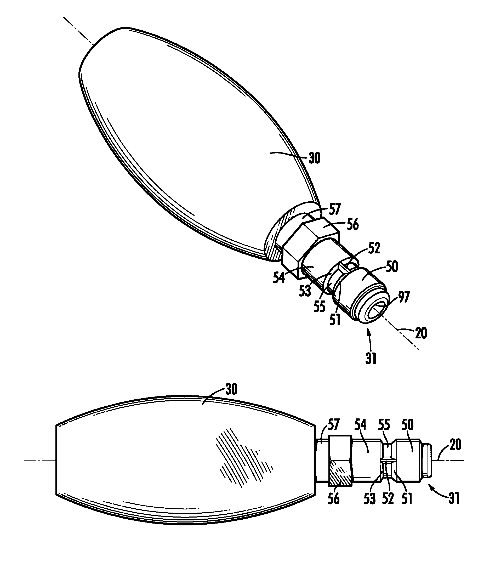
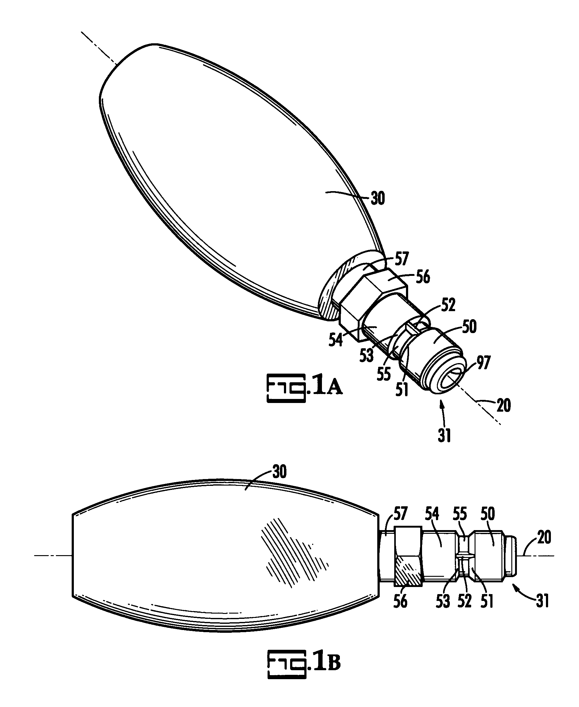
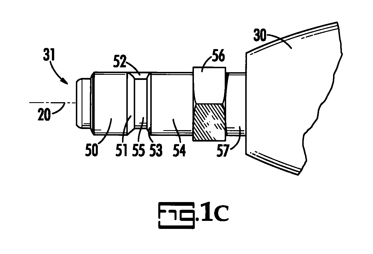
[0023]Male connector 31 includes an internally or externally threaded portion 57 forming an attachment end integrally connected to a male plug or coupling portion or end 50 by means of a shoulder portion 54 intermediate the length of the plug 31. Male plug 31 further includes a fluid or air channel 97 which extends either partially or completely through the male connector 31, one...


PUM


Abstract

The invention is a quick connect and disconnect coupling which limits the free rotation between the female socket and the male plug of the coupling with respect to one another. It comprises a male plug having a coupling end and a female socket having a coupling end with a receiving opening therein to receive the coupling end of the male plug when the connectors are in a coupled condition. A holding mechanism is associated with the ed. The male plug includes a non circular surface that interengages the locking balls within the female quick connect socket to substantially prevent relative rotation of the male plug in relation to the female socket. The coupling is particularly useful for attaching accessories as used in highly pressurized spray applications to allow the ability to rotationally adjust the dispensing action.

Description

CROSS REFERENCE TO RELATED PATENTS[0001]The priority benefit of U.S. Provisional application U.S. 60 / 897,883 filed Jan. 29, 2007, is claimed.BACKGROUND OF THE INVENTION[0002]The present invention is in the field of quick connect couplers.[0003]Quick connect couplers are well known and commonly used in connecting air powered tools to highly pressurized spraying systems. Quick connect couplers allow a user to merely push two portions of the coupler together to connect a fluid or gas line. Numerous types of quick connect couplers exist in the art. These couplers are usually designed to be freely rotatable around a center axis. The problem with such couplers is that there exist applications where minimal, or no rotatable action is desired. In some dispensers, for example, accessories exist that require the user to rotate the nozzle in order to adjust the spray pattern. Traditionally configured couplers do not allow the convenient use of such accessories in a quick connect configuration ...

Claims


Application Information

Patent Timeline
Patent Type & Authority Applications(United States)
IPC IPC(8): F16L37/00
CPCB05B1/12B05B15/065B05B1/005F16L37/23F16L37/22B05B15/65
Inventor WHITE, DAVIS A.
Owner WHITE DAVIS A
Why Eureka
Try Eureka