RFID reader

a reader and reader technology, applied in the field of rfid readers, can solve the problem of relatively short illumination time and achieve the effect of maximising the read probability

Inactive Publication Date: 2008-12-25
SIEMENS AG
View PDF46 Cites 9 Cited by
  • Summary
  • Abstract
  • Description
  • Claims
  • Application Information

AI Technical Summary

Benefits of technology

[0006]A typical gate reader employs several antennas that provide space diversity. First, the tags are interrogated from a first antenna. The majority of the tags, which receive adequate power, will respond. However, the tags which are in the nulls of the interference pattern are missed from the first reading cycle. Next, the tags are interrogated from a second antenna, which is located in a different position. From the second antenna, the multipath pattern is different and those tags which were in a null previously are now likely to be energized adequately. The interrogation is repeated, switching all antennas in a sequential fashion and therefore maximising the read probability.

Problems solved by technology

This is particularly the case in fast moving applications, or in cases where the tags are buried in the shadow of conductive items and therefore the illumination time is relatively short.

Method used


Image

  • RFID reader
  • RFID reader
  • RFID reader

Examples


Embodiment Construction

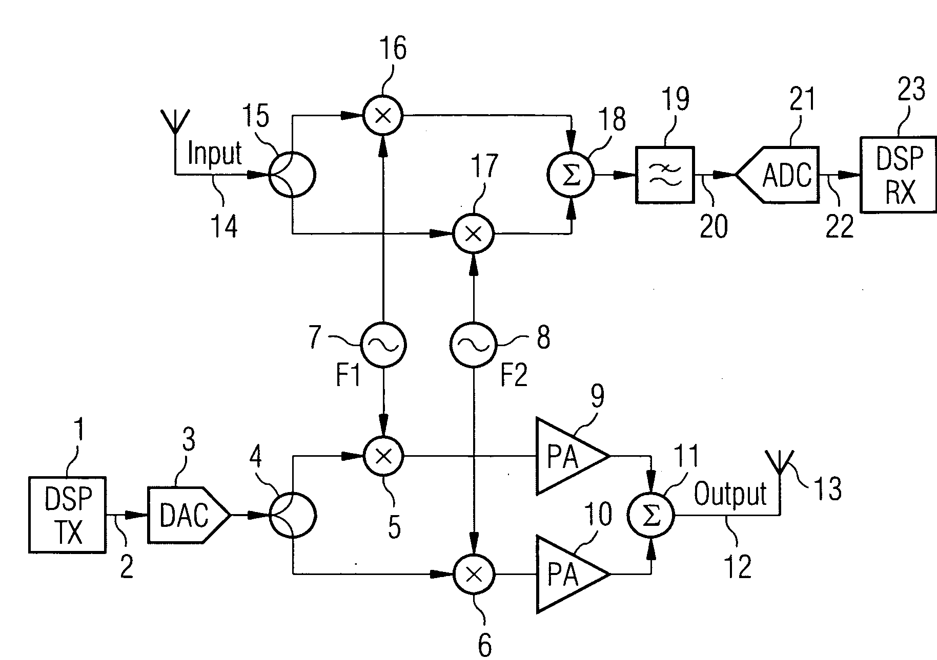
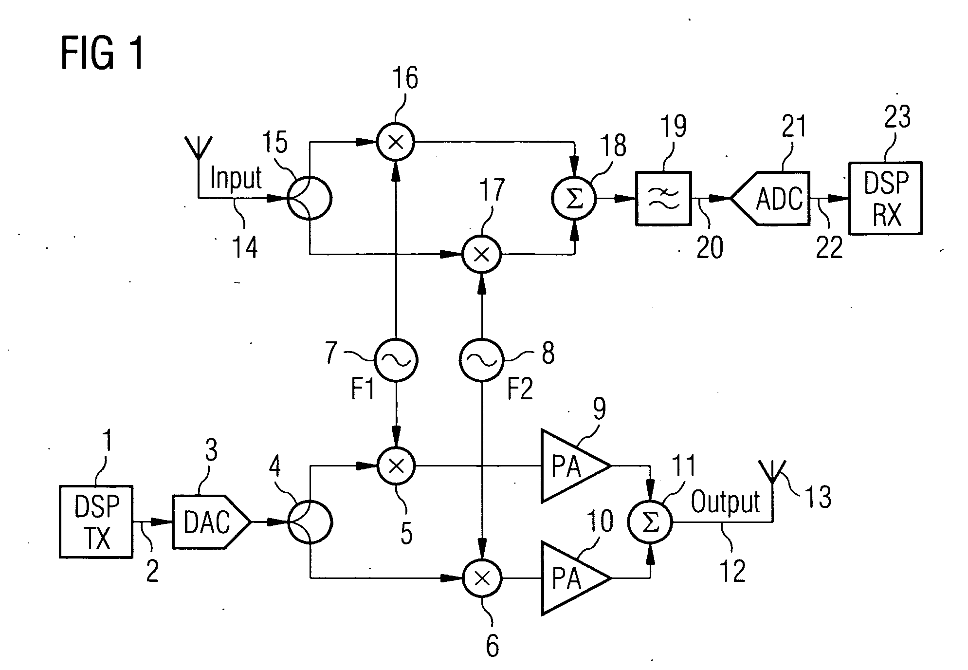
[0032]FIG. 1 shows an example of a multicarrier reader according to the present invention in which the reader transmits and receives on two frequencies simultaneously. This example shows an implementation of the multicarrier architecture in the analog (RF) domain. A transmit baseband signal is generated in a digital signal processor (DSP) section 1 and then applied 2 to the digital to analogue converter 3. Up to this point the functionality of the multicarrier reader is the same as that in the single carrier architecture.

[0033]The baseband signal is split 4 and up-converted to F1 and F2 frequencies using two quadrature up-converters 5, 6 which are fed with F1 and F2 signals from respective local oscillators 7, 8. The up-converted signals are amplified 9, 10 summed 11 and and output 12 applied to an antenna 13.

[0034]For simplification, in FIG. 1 the complex I and Q paths are not shown separately. Each device is duplicated in the actual transceiver processing two independent, I and Q ...


PUM


Abstract

An RFID reader comprises a receiver section for receiving an RF signal and a transmitter section for transmitting an RF signal. The reader is a multicarrier RFID reader and both the transmitted RF signal and the received RF signal comprise at least two frequencies.

Description

CROSS REFERENCE TO RELATED APPLICATIONS[0001]This application claims priority of United Kingdom Patent Office application No. 0709313.1 GB filed May 15, 2007 and of United Kingdom Patent Office application No. 0802055.4 GB filed Feb. 05, 2008, which are incorporated by reference herein in their entirety.FIELD OF INVENTION[0002]The mass application of passive ultra high frequency (UHF) radio frequency identification (RFID) systems is becoming widespread in the retail industry, logistics and commerce. In most applications, it is very important that all tags are interrogated successfully during an inventory round, and no tags are missed. Despite efforts in improving the performance of the current RFID systems, 100% success rate has not yet been reached in some applications.BACKGROUND OF INVENTION[0003]In passive RFID systems the tags receive their power from the RF field transmitted by the reader. The efficiency of the power transfer from the reader to the tags is essential for reliabl...

Claims


Application Information

Patent Timeline
Patent Type & Authority Applications(United States)
IPC IPC(8): H04Q5/22
CPCG06K7/0008H04B7/04H04L27/2601G06K7/10366G01V15/00G08B13/14G08B13/149G08B13/24
Inventor DOMOKOS, JOHNHORST, DIETER
Owner SIEMENS AG
Why Eureka
Try Eureka