Adaptive detector arrays for optical communications receivers

a technology of optical communication receiver and detector array, which is applied in the direction of transmission monitoring, line-of-sight transmission, electromagnetic transmission, etc., can solve the problems of reducing the effective diameter of the receiving telescope, reducing and affecting the operation of large telescopes in atmospheric conditions that rarely permit diffraction-limited operation, etc., to achieve the effect of maximizing the probability of correct detection

Inactive Publication Date: 2006-06-06
CALIFORNIA INST OF TECH
View PDF14 Cites 32 Cited by
  • Summary
  • Abstract
  • Description
  • Claims
  • Application Information

AI Technical Summary

Benefits of technology

[0012]In the above embodiments, several possible algorithms can be applied via the signal processing assembly to combine the detector outputs advantageously, i.e., to maximize the probability of correct detection. For example, in one embodiment, a logarithmic function of the ratio of signal and noise energies is applied to each output for a short time corresponding to the coherence-time of the channel. In an alternative embodiment, a time-varying “mask” is computed and applied to the array such that only those elements of the array with the greatest signal content are utilized.

Problems solved by technology

It is well known that ground-based reception of optical signals suffers from degradation of the optical phase-front caused by atmospheric turbulence.
This turbulence leads to a reduction in the effective diameter of the receiving telescope, and to random fluctuations of the receiver's “point spread function” (PSF) in the focal plane.
However, atmospheric conditions rarely permit diffraction-limited operation of large telescopes; even under “good” nighttime seeing conditions, the phase of the received signal field tends to become uncorrelated over distances greater than 20 cm, deteriorating to as little as 2 to 4 cm during the day.
However, this increase in the receiver's FOV leads to a corresponding increase in the amount of interfering background radiation offsetting much of the performance gain.
However, due to the limitations of the chosen algorithms and the electronics utilized, only the average PSF of the received signals over a relatively long time period have been successfully processed.
Although some performance improvement has been seen from receivers utilizing these time-average PSF signal-processing techniques, because the PSF can change on the order of milliseconds much of the detailed information from the processed transmissions is lost.

Method used


Image

  • Adaptive detector arrays for optical communications receivers
  • Adaptive detector arrays for optical communications receivers
  • Adaptive detector arrays for optical communications receivers

Examples


Embodiment Construction

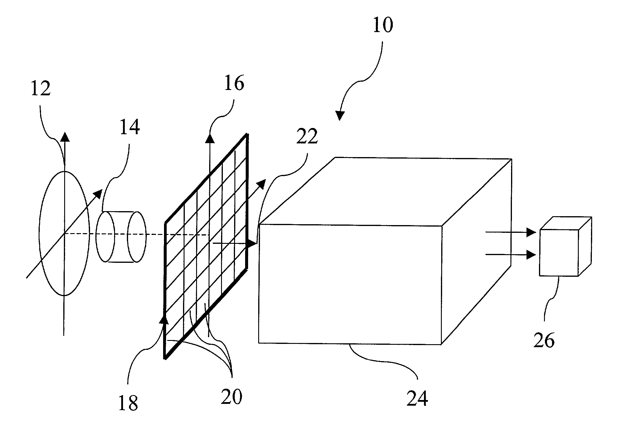
[0033]The present invention is directed to an optical communications receiver comprising a wide-band optical detector array and a high-speed digital signal processor assembly programmed to operate on the raw data from the detector array to ameliorate the effects of atmospheric turbulence on the performance of the optical receiver in real-time while operating within the terrestrial atmosphere, or while attempting to communicate through any similar turbulent medium.

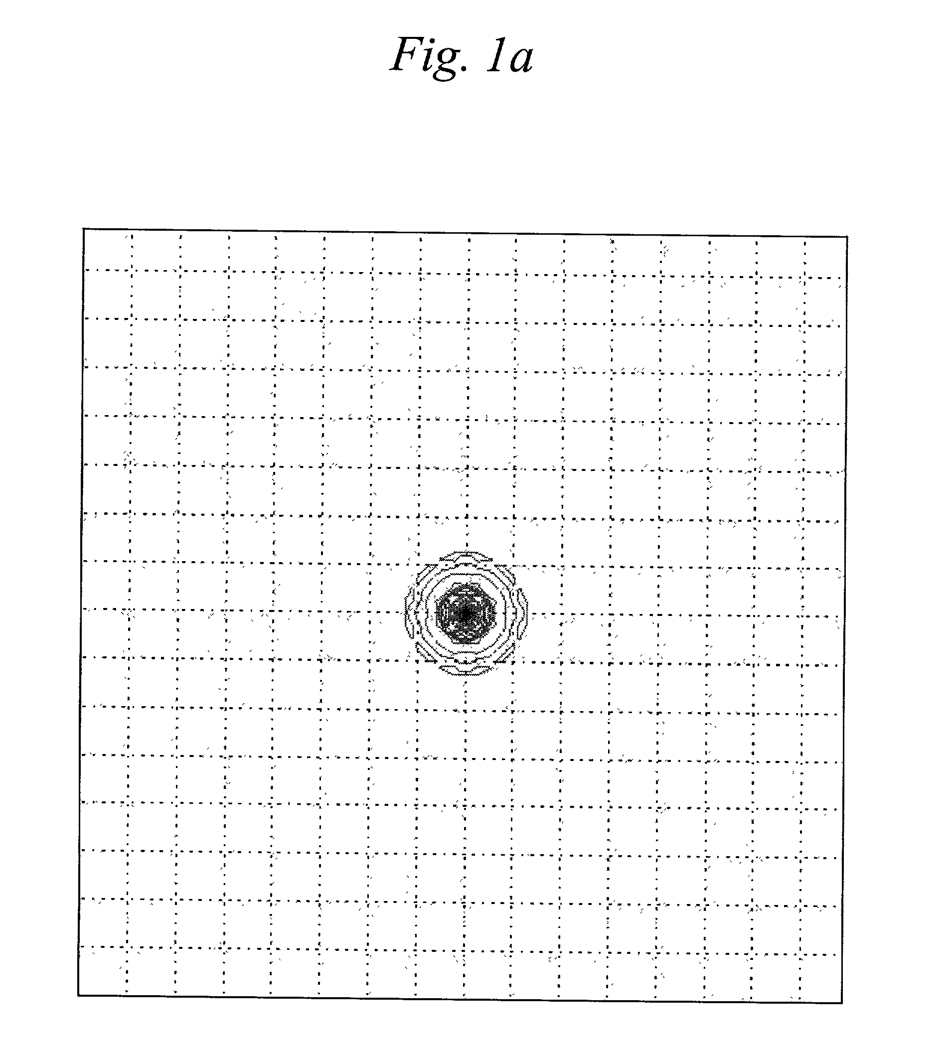
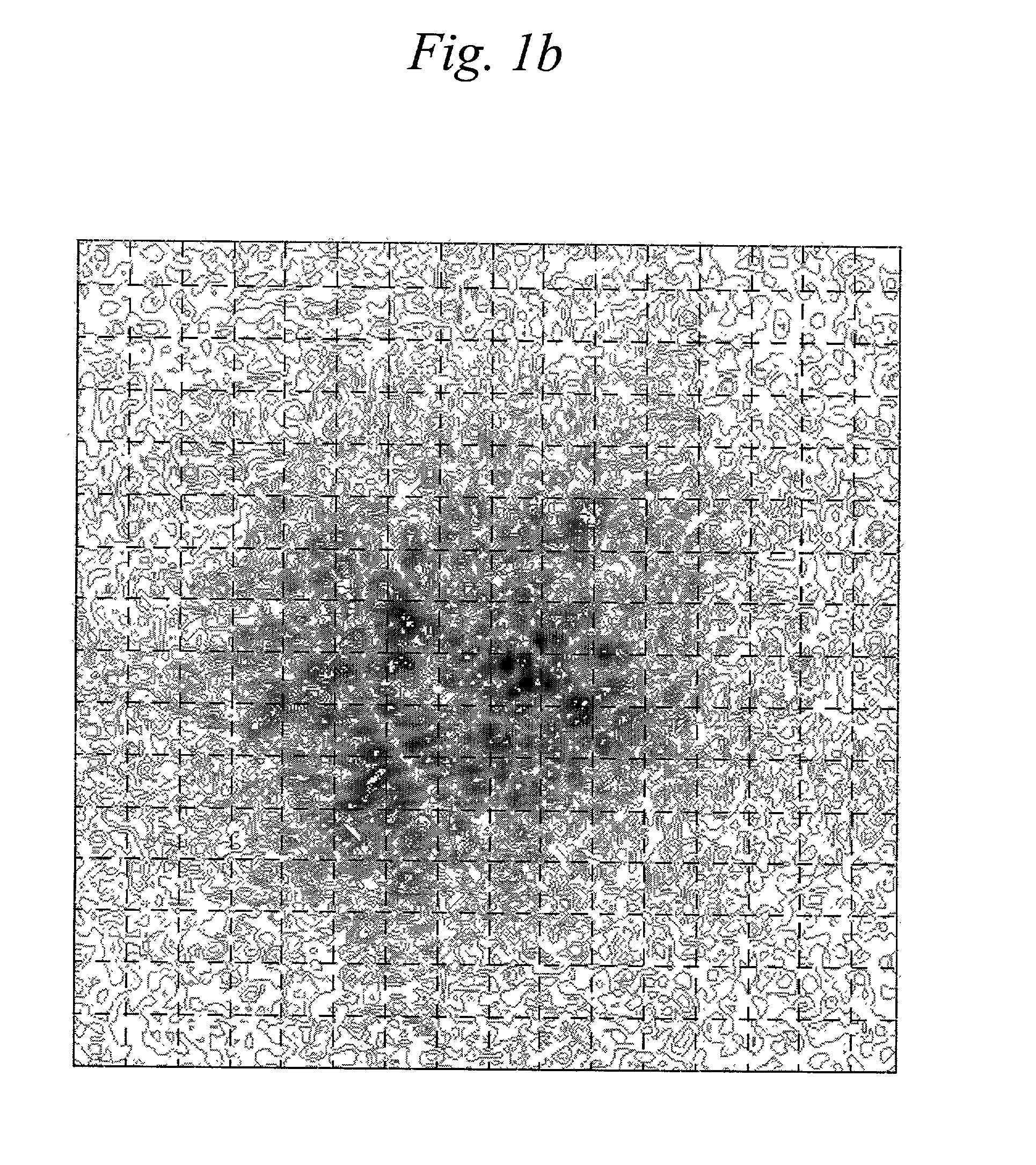
[0034]An example of the increase in the effective dimensions of an exemplary receiver point-spread function over its diffraction-limited value as a result of atmospheric turbulence is shown by comparison in FIGS. 1a and 1b. The hypothetical signal shown in these figures correspond to a telescope having a 1 m aperture, an 0.3 m central obstruction, and a 4 cm atmospheric coherence. As shown in FIG. 1a, under ideal conditions the undistorted signal generates a diffraction limited point spread function (PSF) in the detector ar...


PUM


Abstract

An optical communications receiver comprising a wide-band optical detector array and a high-speed digital signal processor programmed to operate on the raw data from the detector array to ameliorate the effects of atmospheric turbulence on the performance of the optical receiver in real-time while operating within the terrestrial atmosphere, or while attempting to communicate through any similar turbulent medium is provided. A method of sending optical communications through such optical communications receivers is also provided.

Description

CROSS-REFERENCE TO RELATED APPLICATION(S)[0001]This application claims the benefit of U.S. provisional application No. 60 / 253,610 filed on Nov. 28, 2000, the content of which is incorporated herein by reference.STATEMENT REGARDING FEDERALLY SPONSORED RESEARCH OR DEVELOPMENT[0002]The U.S. Government has certain rights in this invention pursuant to grant No. NAS7-1407, awarded by the National Aeronautical and Space Administration.FIELD OF THE INVENTION[0003]This invention is directed to improved optical receivers, and particularly to high data-rate optical receivers utilizing wide-band optical detector arrays capable of correcting for signal degradation caused by atmospheric turbulence.BACKGROUND OF THE INVENTION[0004]It is well known that ground-based reception of optical signals suffers from degradation of the optical phase-front caused by atmospheric turbulence. This turbulence leads to a reduction in the effective diameter of the receiving telescope, and to random fluctuations of ...

Claims


Application Information

Patent Timeline
Patent Type & Authority Patents(United States)
IPC IPC(8): H04B10/06H04B10/08H04B10/10
CPCH04B10/112
Inventor VILNROTTER, VICTORSRINIVASAN, MEERA
Owner CALIFORNIA INST OF TECH
Why Eureka
Try Eureka