

Ultrasonic diagnostic apparatus and method of controlling the same
a diagnostic apparatus and ultrasonic technology, applied in ultrasonic/sonic/infrasonic diagnostics, instruments, applications, etc., can solve the problems of difficult to clearly distinguish operators, difficult to extract such a lesion from images, and misleading image information of speckle patterns
- Summary
- Abstract
- Description
- Claims
- Application Information
AI Technical Summary
Benefits of technology
Problems solved by technology
Method used
Image

Examples
first embodiment
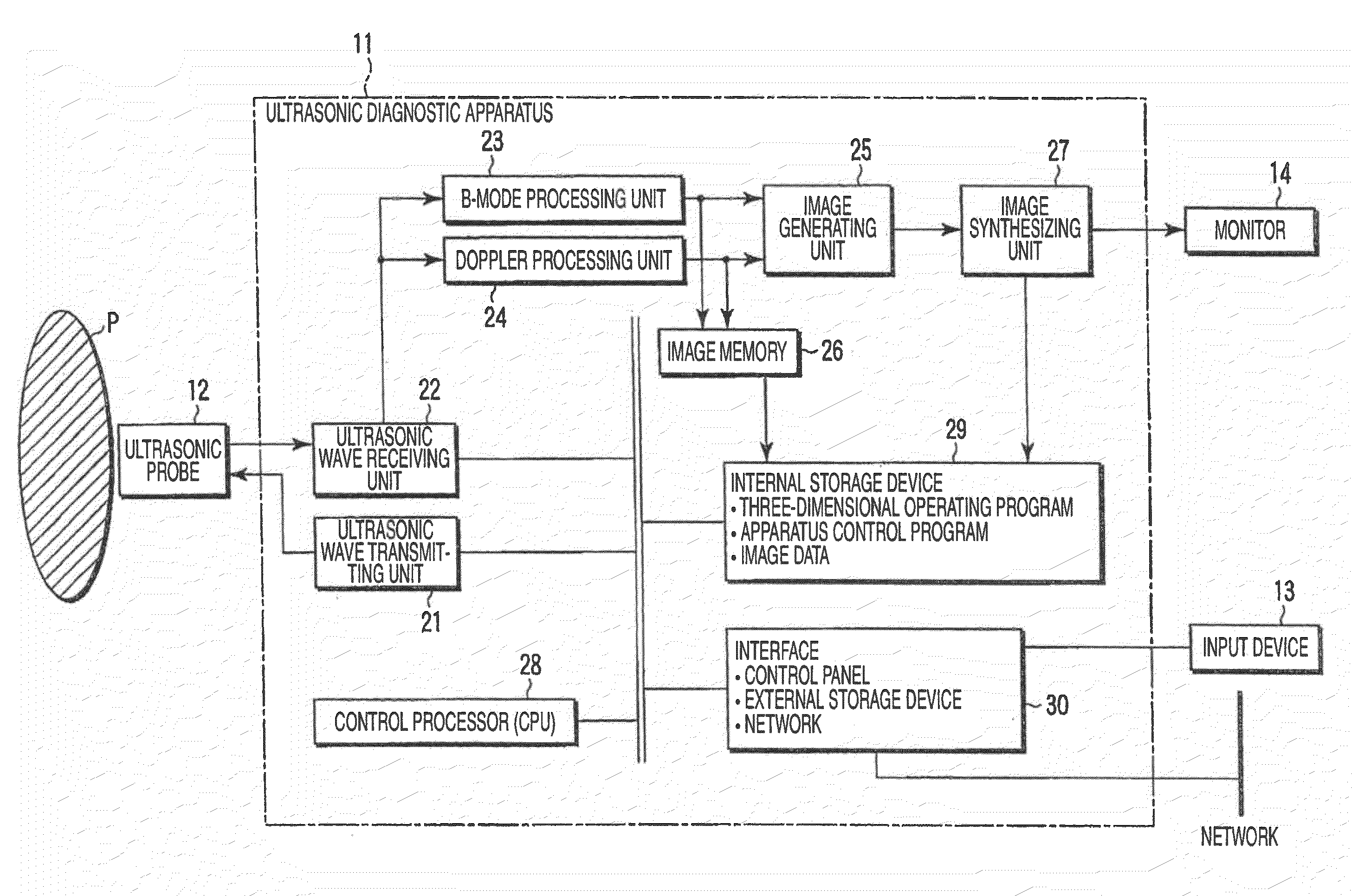
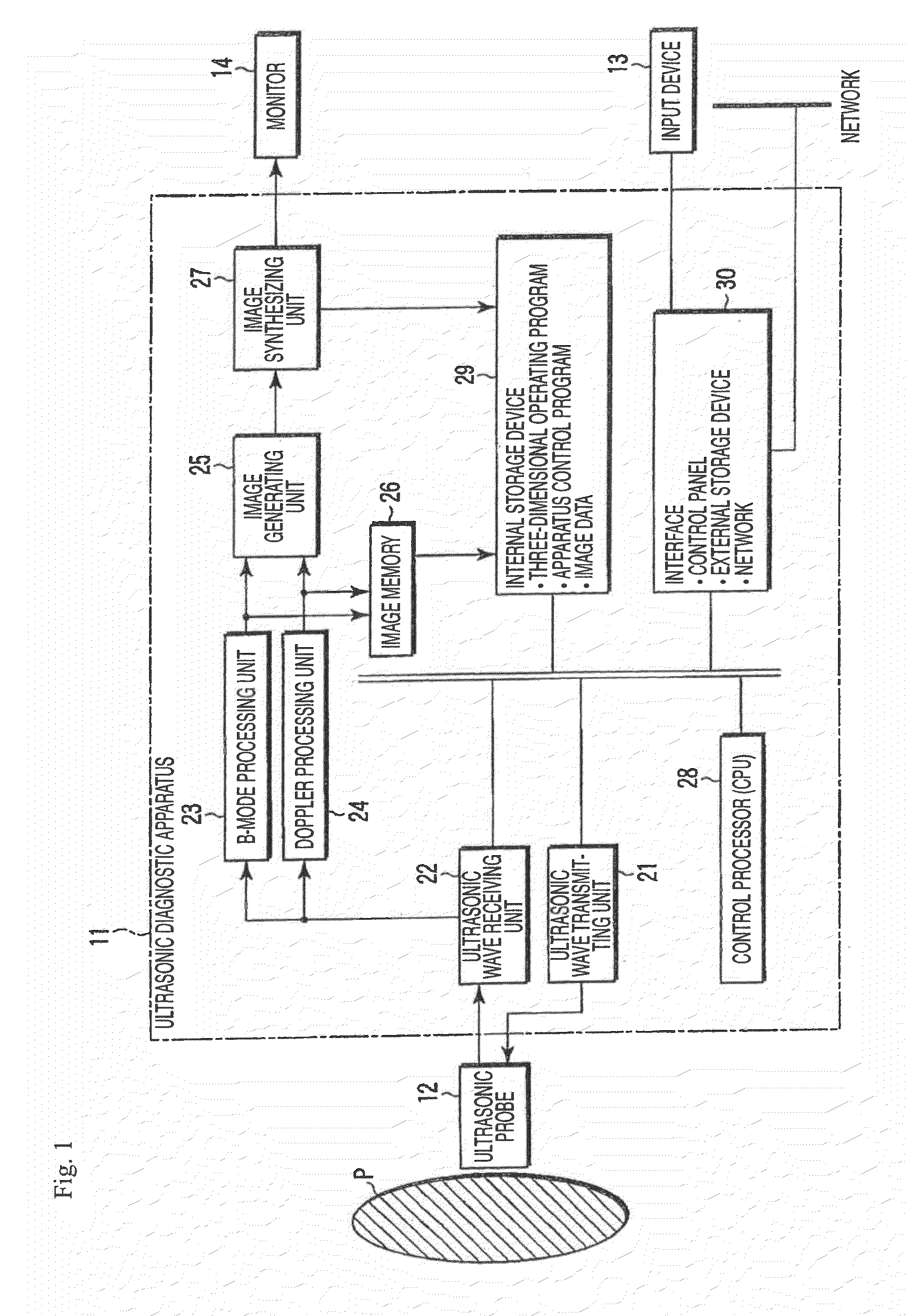
[0050]FIG. 1 is a block diagram illustrating the structure of an ultrasonic diagnostic apparatus according to a first embodiment of the invention. As shown in FIG. 1, an ultrasonic diagnostic apparatus 11 according to this embodiment includes an ultrasonic probe 12, an input device 13, a monitor 14, an ultrasonic wave transmitting unit 21, an ultrasonic wave receiving unit 22, a B-mode processing unit 23, a Doppler processing unit 24, an image generating unit 25, an image memory 26, an image synthesizing unit 27, a control processor (CPU) 28, an internal storage unit 29, and an interface 30. Hereinafter, the functions of the components will be described.
[0051]The ultrasonic probe 12 includes a plurality of piezoelectric vibrators that generate ultrasonic waves on the basis of a driving signal from the ultrasonic wave transmitting unit 21 and convert reflected waves from a subject into electric signals, a matching layer that is provided in each of the piezoelectric vibrators, and a b...
second embodiment
[0089]Next, a second embodiment of the invention will be described.
[0090]The structure of an ultrasonic diagnostic apparatus according to the second embodiment is substantially the same as that shown in FIG. 1. Hereinafter, only different functions from those in the first embodiment will be described.
[0091]An image generating unit 25 performs a process related to a microstructure extracting function (microstructure extracting process) according to this embodiment.
[0092]A control processor 28 reads from an internal storage unit 29 a dedicated program for implementing the microstructure extracting function according to this embodiment, expends the read program on its own memory, and performs predetermined arithmetic and control processes.
[0093](Microstructure Extracting Function)
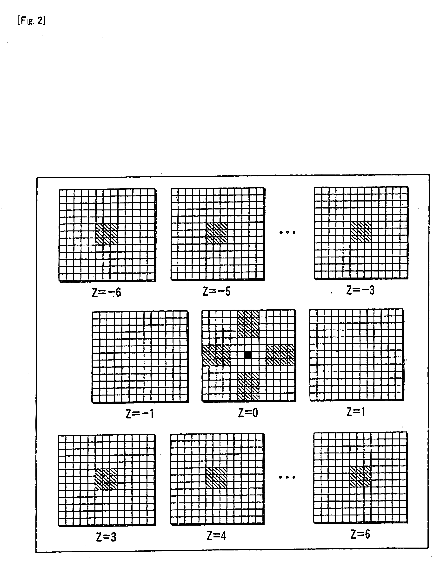
[0094]The microstructure extracting function according to this embodiment performs the microstructure extracting process using a process for removing a speckle pattern and a depth-direction arithmetic process ...
third embodiment
[0116]Next, a third embodiment of the invention will be described. The third embodiment differs from the second embodiment in that the process of removing a speckle pattern is not performed, but the depth-direction arithmetic process is directly performed using N two-dimensional images.
[0117]FIG. 11 is a flowchart illustrating the flow of a microstructure extracting process according to this embodiment. As shown in FIG. 11, first, the image generating unit 25 receives three-dimensional image data composed of N two-dimensional images, which are targets, and stores the image data in a predetermined memory (Step S21).
[0118]Then, the image generating unit 25 uses each of the two-dimensional images to perform the depth-direction arithmetic process, thereby generating a microstructure extracted image (Step S22). The generated microstructure extracted image is displayed on the monitor 14 by the image synthesizing unit 27 and is automatically stored in, for example, the internal storage uni...
PUM
 Abstract
Description
Claims
Application Information