
Hydraulic Connector and a Hydraulic Circuit Incorporating the Connector

a technology of hydraulic circuits and connectors, applied in the direction of bends, couplings, siphons, etc., can solve the problems of increasing the complexity and number of circuits inside the machine, the flow conditions inside the circuitry, and the hydraulic circuits in the dialysis machine are subject to high fluid flow, so as to achieve the effect of not losing the anchoring and sealing efficiency

Active Publication Date: 2009-01-01
GAMBRO LUNDIA AB
View PDF33 Cites 4 Cited by
  • Summary
  • Abstract
  • Description
  • Claims
  • Application Information

AI Technical Summary

Benefits of technology

[0019]A first aim of the invention is to make available a connector for hydraulic circuits which can be used in medical machines and which offers optimal mechanic seal and fluid seal for fluids which are not in stationary flow conditions, and in particular in the presence of sometimes sharp variations in flow direction across the connector.
[0021]Additionally, an aim of the invention is to make available a connector that can be made with complex configurations, without losing anchoring and seal efficiency.

Problems solved by technology

Apart from the above-mentioned blood line and dialyser liquid preparation line, there might also be circuits destined to enable effecting of preparation of other liquids, such as medical or replacement liquids, as well as further circuits or lines for discharging the used liquid, for the control of ultrafiltration, or other lines, safety lines and / or washing lines which further increase the complexity and number of circuits internally of the machine.
Firstly, an important observation is that hydraulic circuits in dialysis machines are subject to high quantities of fluid flow.
The particular types of treatment to be performed, but also the washing and sterilising operations on the circuits themselves, lead to flow conditions inside the circuitry which are such as to generate considerable stress thereon, especially at the connections and especially when flow is inverted.
This can lead to serious problems during treatment of a patient, but can also have dire consequences for the electrical or electronic apparatus which the machine is equipped with.
Furthermore it is obvious that even simple changes in relative positions between the tube and the connector can lead to an imperfect fluid seal, with the attendant risk that fluid can leak out and damage the apparatus.

Method used


Image

  • Hydraulic Connector and a Hydraulic Circuit Incorporating the Connector
  • Hydraulic Connector and a Hydraulic Circuit Incorporating the Connector
  • Hydraulic Connector and a Hydraulic Circuit Incorporating the Connector

Examples


Embodiment Construction

[0024]The description will be made with reference to the accompanying figures of the drawings, provided by way of non-limiting example, in which:

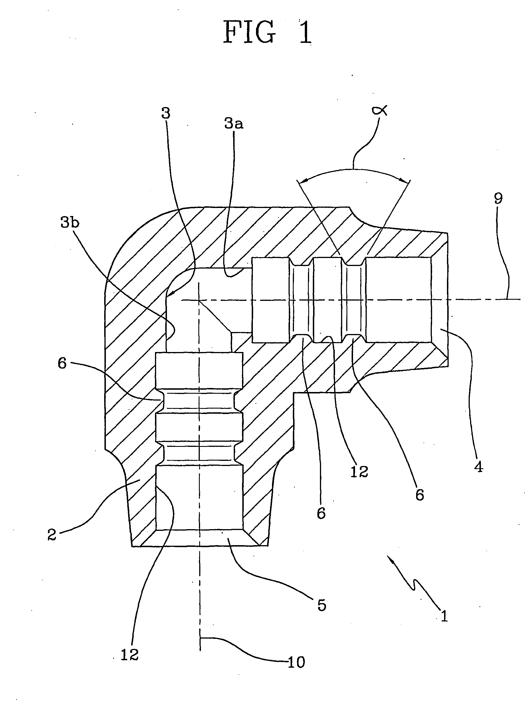
[0025]FIG. 1 is a section of the hydraulic connector of the invention;

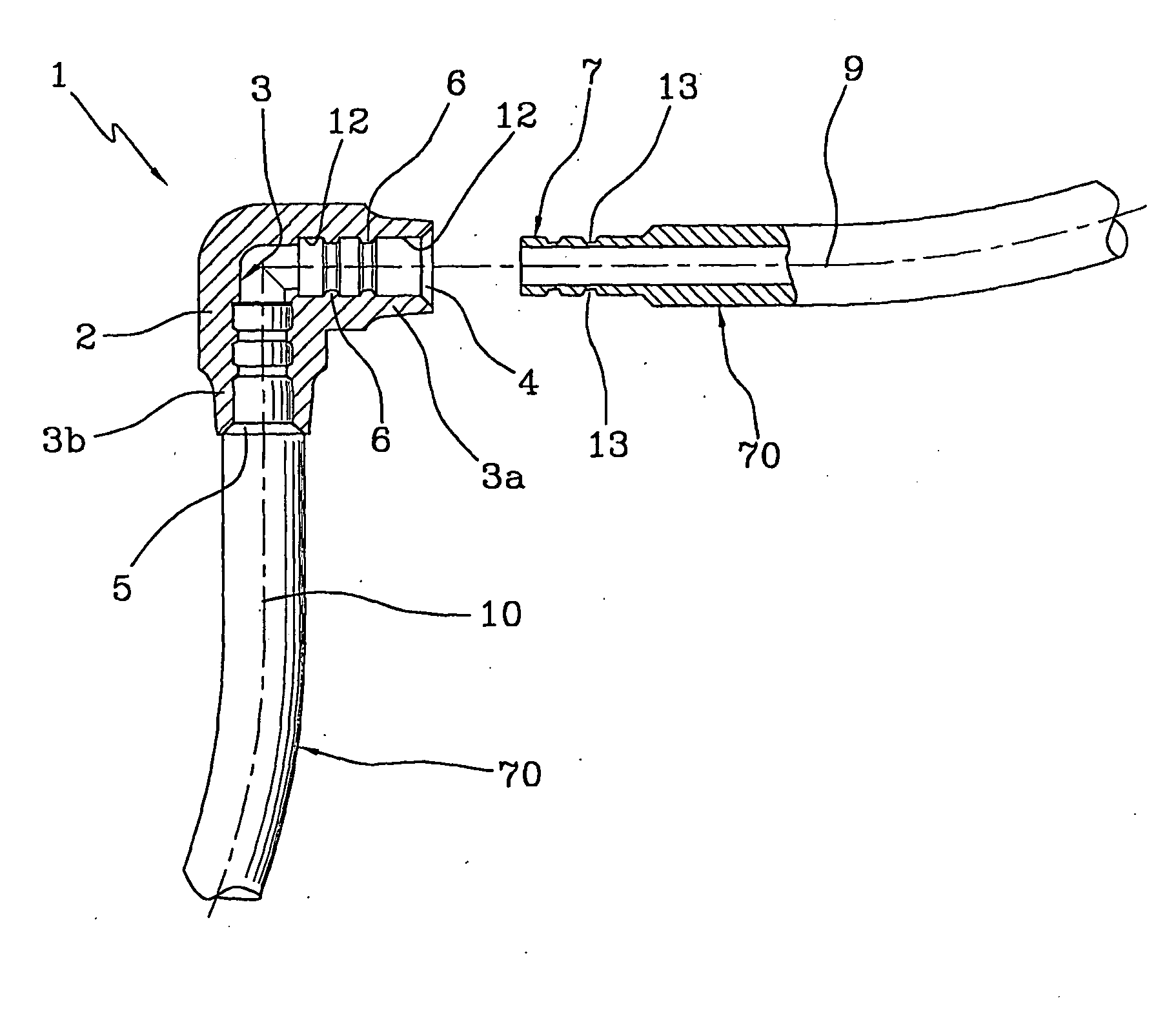
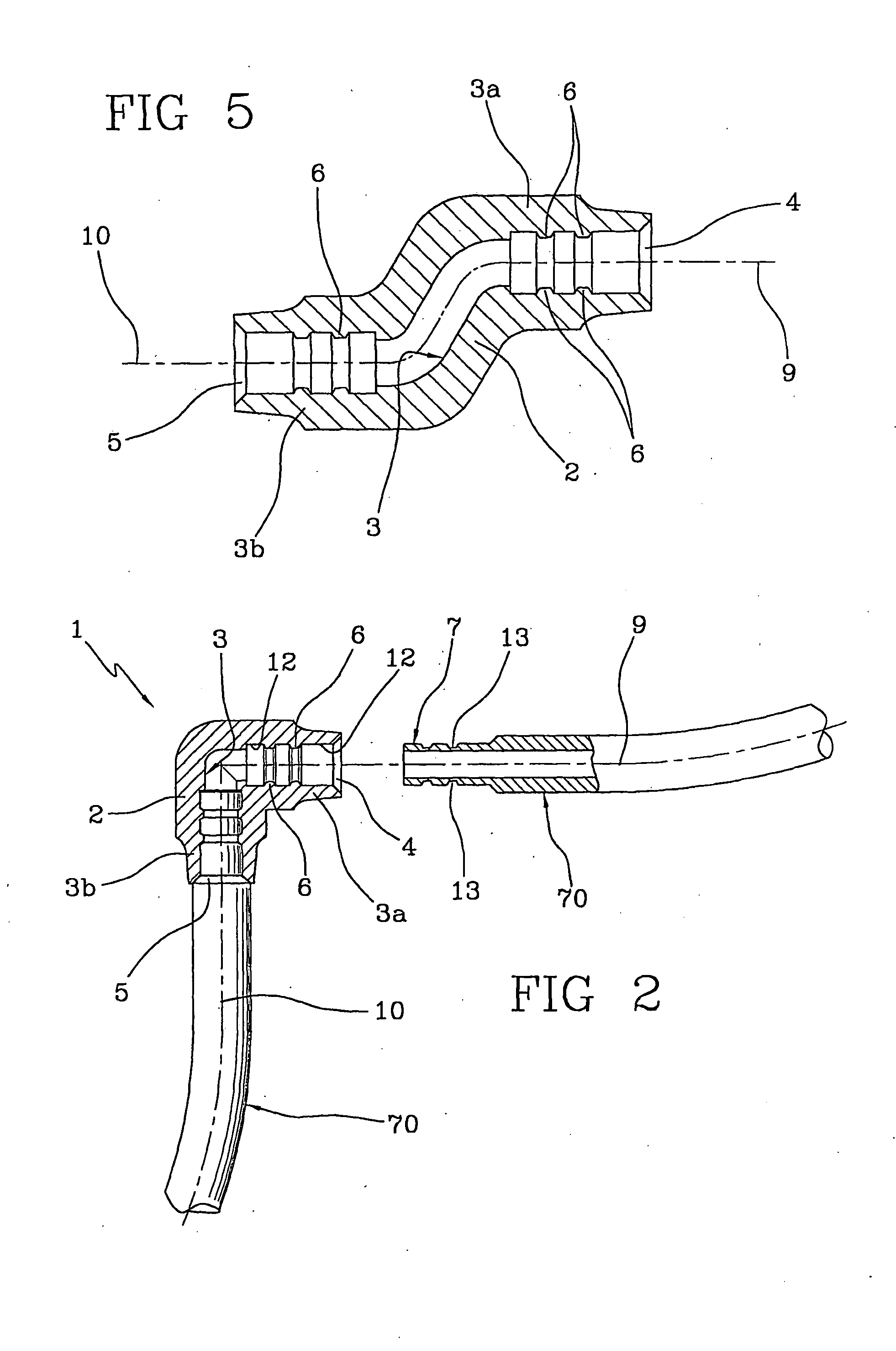
[0026]FIG. 2 shows the connector in a coupled connection with a port of a tube;

[0027]FIG. 3 is the example of FIG. 2 in perspective view;

[0028]FIG. 4 illustrates a T-shaped connector of the invention;

[0029]FIG. 5 is a possible further embodiment of the connectors of the invention;

[0030]FIG. 6 is an extremely schematic view of a machine for extracorporeal blood treatment in which the connector and the hydraulic circuit of the invention can be used; and

[0031]FIG. 7 is a schematic illustration of a portion of a hydraulic circuit, in which various hydraulic components are connected by connectors of the invention.

[0032]With reference to the figures of the drawings, 1 denotes in its entirety a hydraulic connector made of an elastically deformable material. The connector is usab...


PUM


Abstract

A hydraulic connector made entirely of an elastomeric material connects tubes or other hydraulic circuit components used in machines for extracorporeal blood treatment. The hydraulic connector comprises a main body (2), which defines a conduit (3), and a predetermined number of protuberances (6) fashioned to enable a stable engagement of the connector to an end of a tubular port (7) of tubing or other hydraulic component. The conduit (3) exhibits a first longitudinal portion (3a) directed along a first development axis (9) and a second longitudinal portion (3a) directed along a second development axis (10); the axes (9, 10) do not coincide.

Description

TECHNICAL FIELD[0001]The invention relates to a hydraulic connector made of an elastically deformable material, destined to place in communication a predetermined number of components belonging to a hydraulic circuit, which connector is advantageously usable in medical applications such as machines for extracorporeal blood treatment.BACKGROUND ART[0002]As is known, medical devices at present in use for treatment of kidney problems, and especially for extracorporeal blood treatment, are constituted by complex apparatus which internally comprise hydraulic circuits for managing the various patient treatment operations.[0003]By way of mere non-exhaustive example, dialysis machines at present in use comprise a blood circuit destined to remove blood from the patient and to bring it to a treatment unit. Once treated the blood is returned to the patient. In general, the above-described circuit is accompanied by a preparation line of a treatment fluid which brings a dialyser liquid into a si...

Claims


Application Information

Patent Timeline
Patent Type & Authority Applications(United States)
IPC IPC(8): F16L37/08
CPCA61M1/1656F16L37/025A61M39/10A61M1/1668
Inventor VINCI, LUCA
Owner GAMBRO LUNDIA AB
Learn More