Rotor structure

a rotor and structure technology, applied in the direction of stator/rotor body manufacturing, magnetic circuit rotating parts, magnetic circuit shape/form/construction, etc., can solve the problems of deteriorating workability, difficult to fill adhesive into the gap, and shaft cannot be securely fixed to the magn

Active Publication Date: 2009-01-01
MINEBEAMITSUMI INC
View PDF6 Cites 29 Cited by
  • Summary
  • Abstract
  • Description
  • Claims
  • Application Information

AI Technical Summary

Benefits of technology

[0016]The present invention has been made in light of the above problems, and it is an object of the present invention to provide a rotor, in which a shaft is securely fixed to a magnet by adhesive, and the amount of adhesive filled in a gap between the shaft and the magnet can be readily determined.
[0021]According to the present invention, a rotor is provided, in which a shaft is securely fixed to a magnet by adhesive, and the amount of adhesive filled in a gap between the shaft and the magnet can be readily determined.

Problems solved by technology

Also, since even a portion of the adhesive that is required to duly fix the shaft to the magnet is not introduced into the gap between the shaft and the magnet, it happens that the shaft can not be kept securely fixed to the magnet.
In this method, however, due to the adhesive 105 filled in the gap between the inner circumferential surface of the hole 103 and the outer circumferential surface of the shaft 102, it may happen that the magnet 101 and the shaft 102 are not disposed coaxial with each other, in which case the rotor has a runout thereby causing vibration.
In order to deal with this runout problem, the magnet 101 and the shaft 102 must be supported by a tool coaxially with each other until the adhesive 105 is cured, which results in a deteriorated workability.
In the structure of the rotor described above, however, the gap between the shaft 220 and the curved segments 216 is small, and consequently it is difficult to fill adhesive into the gap.
Also, it is difficult to know the amount of adhesive which is introduced in the gap between the shaft 220 and the curved segments 216.

Method used


Image

  • Rotor structure
  • Rotor structure
  • Rotor structure

Examples


Embodiment Construction

[0032]An exemplary embodiment of the present invention will be described with reference to the accompanying drawings.

[0033]The present invention relates to a structure of a rotor for a PM stepping motor, and therefore explanations and drawings of other portions of the PM stepping motor are omitted.

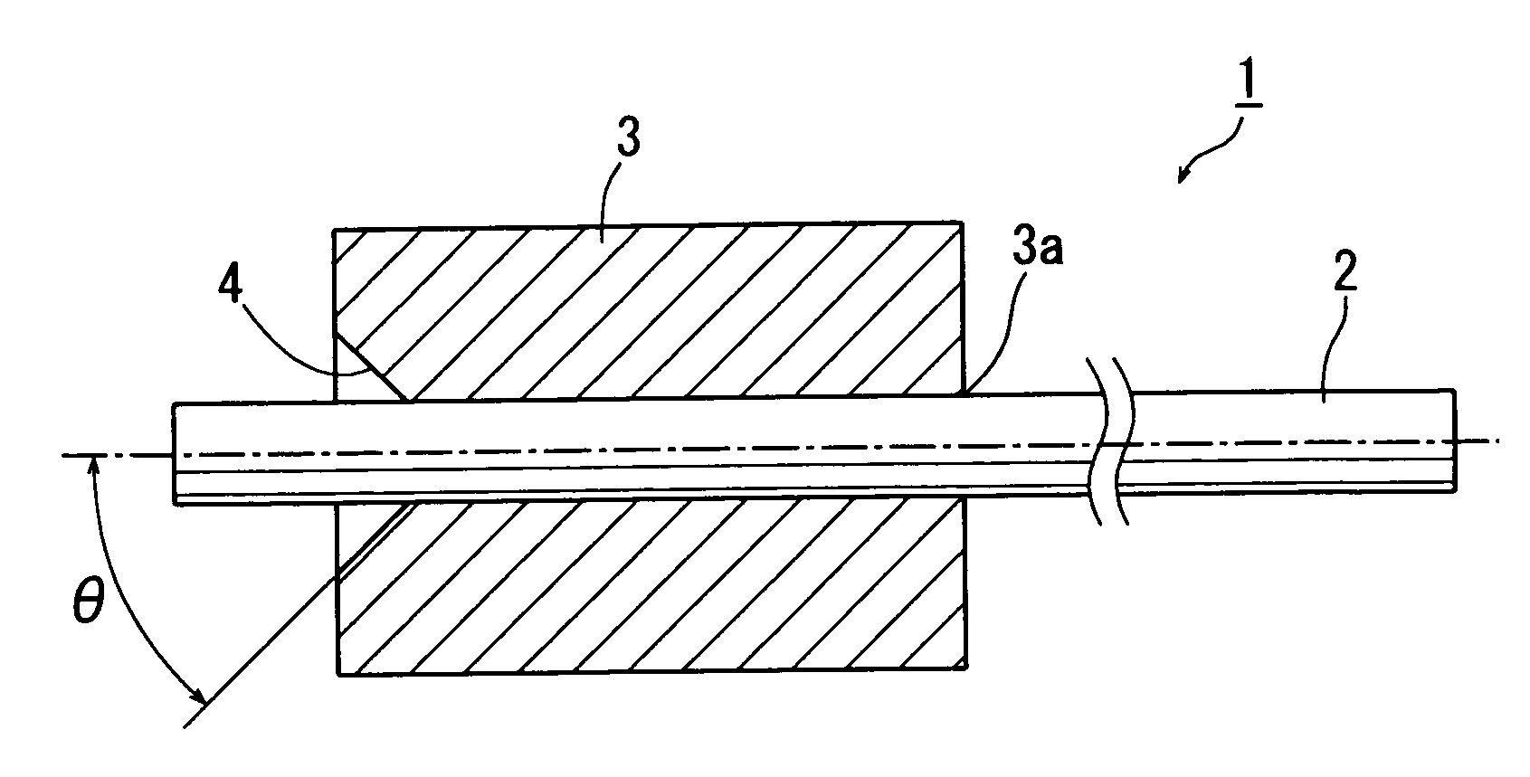
[0034]Referring to FIG. 4, a rotor 1 according to an embodiment of the present invention includes a shaft 2 and a magnet 3 attached to the shaft 2. The shaft 2 is a round bar made of metal, and the magnet 3 is an Nd—Fe—B bonded magnet having a circular cylinder shape and having its outer circumference multipole-magnetized in the circumferential direction.

[0035]The cylindrical magnet 3 has a hole 3a formed through its axial center, and a recess 4 having a truncated cone shape is formed at one axial end of the magnet 3 so as to communicate with the hole 3a. The hole 3a has a regular hexagonal shape in radial cross section defining six flat portions 3b and six angle portions 3c as shown in FI...


PUM


Abstract

A rotor includes: a magnet having a circular cylinder shape and having a hole formed through its axial center, wherein the hole has in axial cross section a regular polygonal shape having flat portions and angle portions, and wherein a recess having a truncated cone shape is disposed at an axial end of the magnet such that the recess has its maximum diameter portion located at the axial end and has its minimum diameter portion communicating with the hole; and a shaft fitted in the hole of the magnet, wherein the outer circumference of the shaft makes contact with the flat portions of the hole of the magnet thereby forming a plurality of gaps between the outer circumference of the shaft and the angle portions of the hole of the magnet, and adhesive is filled in the gaps.

Description

CROSS-REFERENCE TO RELATED APPLICATIONS[0001]This application claims priority to Japanese Patent Application No. 2007-167399, filed Jun. 26, 2007, which is expressly incorporated herein by reference and made a part hereof.FEDERALLY SPONSORED RESEARCH OR DEVELOPMENT[0002]Not Applicable.TECHNICAL FIELD[0003]The present invention relates to a structure of a rotor incorporated in, for example, a small permanent magnet (PM) stepping motor.BACKGROUND OF THE INVENTION[0004]As electric equipments are becoming smaller and smaller, a stepping motor of claw pole type (so-called “PM stepping motor”) for use in such electric equipment is requested to be downsized and also to provide an enhanced performance. Under such circumstances, a rotor magnet must be downsized and also improvement must be sought in the method of fixing a rotor shaft to the magnet.[0005]For example, an Nd—Fe—B bonded magnet having a high magnetic characteristic is commonly used as a rotor magnet, and such a magnet is fixed t...

Claims


Application Information

Patent Timeline
Patent Type & Authority Applications(United States)
IPC IPC(8): H02K15/03
CPCH02K1/28H02K1/2733
Inventor SUZUKI, YUZURUYAMAWAKI, TAKAYUKIFURUSAKI, HIROYUKI
Owner MINEBEAMITSUMI INC
Why Eureka
Try Eureka