Method, system, and apparatus for a core activity detector to facilitate dynamic power management in a distributed system

a distributed system and core activity detector technology, applied in power management, high-level techniques, instruments, etc., can solve the problems that conventional activity detector circuitry cannot effectively hide the latency of turning on/off the unit, and the ptp architecture will likely experience power management difficulties

Inactive Publication Date: 2009-01-01
INTEL CORP
View PDF7 Cites 206 Cited by
  • Summary
  • Abstract
  • Description
  • Claims
  • Application Information

AI Technical Summary

Problems solved by technology

However, pTp architectures will likely experience difficulties in power management.
As a result, conventional activity detector circuitry cannot effectively hide the latency to turn on / off the units from the performance aspects of the system since it cannot provide adequate lead time to circuitry of these units to turn power on or off.

Method used


Image

  • Method, system, and apparatus for a core activity detector to facilitate dynamic power management in a distributed system
  • Method, system, and apparatus for a core activity detector to facilitate dynamic power management in a distributed system
  • Method, system, and apparatus for a core activity detector to facilitate dynamic power management in a distributed system

Examples


Embodiment Construction

[0014]The present application is related to and may incorporate embodiments from two previously filed applications. Both of the previously filed applications were filed on Jun. 29, 2006 by the same set of inventors. The first application, attorney docket P23215, is titled “Method and Apparatus for Dynamically Controlling Power Management in a Distributed System”, Ser. No. 11 / 479,438. The second application, attorney docket P24042, is titled “Method and Apparatus to Dynamically Adjust Resource Power Usage in a Distributed System”, Ser. No. 11 / 479,009.

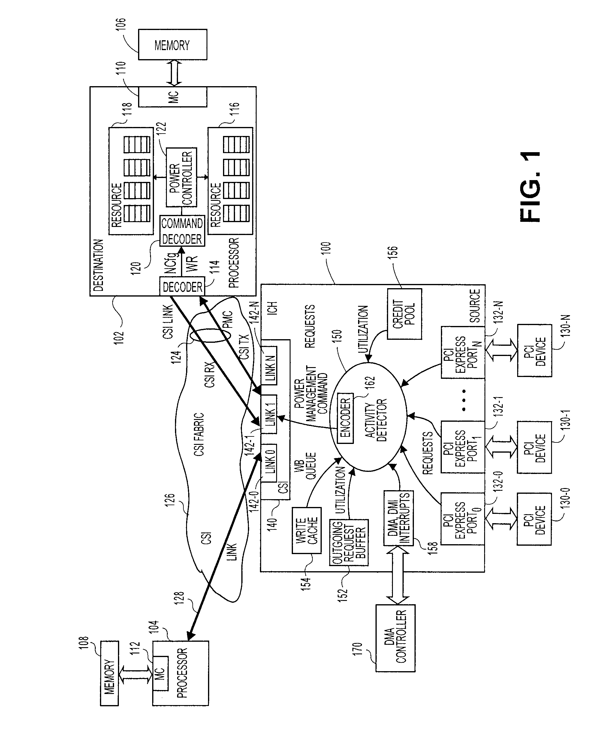
[0015]FIG. 1 is a block diagram of a dual processor system of one embodiment of the invention. Such a dual processor (DP) embodiment and may occur in a variety of possible platforms. For example, this embodiment may be implemented as a desk top or mobile computer, a server, a set top box, a personal digital assistant (PDA), an alphanumeric pager, cellular telephone, or any other type of wireless communication device.

[0016]In this embodim...


PUM


Abstract

A system and method to provide source controlled dynamic power management. An activity detector in a source determines expected future resource usage. Based on that expected usage, the source generates a power management command and sends that command to a destination. The destination then adjusts the power level of the resource based in the command.

Description

BACKGROUND OF THE INVENTION[0001]1. Field[0002]Embodiments of the invention relate to power management. More specifically, embodiments relate to source controlled dynamic power management.[0003]2. Background[0004]Microprocessors commonly use dynamic power management techniques to manage power usage. Normally, dynamic power management for microprocessors is accomplished through activity detector circuitry that is located in the microprocessor and coupled to a centralized, front side bus (FSB). The activity detector circuitry is adapted to detect conditions under which certain units should be turned on or off and to adjust the power levels of these units appropriately.[0005]Traditionally, the activity detector circuitry has provided acceptable performance because such circuitry was physically separated from the power-controlled units by only a short distance. However, bus architectures are moving away from FSB architectures and are beginning to utilize point-to-point (pTp) architectur...

Claims


Application Information

Patent Timeline
Patent Type & Authority Applications(United States)
IPC IPC(8): G06F1/00
CPCG06F1/3203Y02B60/50H04W52/028Y02D30/70H04M1/73
Inventor LIU, YEN-CHENGHUTSELL, STEVEN R.SISTLA, KRISHNAKANTH
Owner INTEL CORP
Why Eureka
Try Eureka