Method of cutting off workpiece using band saw machine as well as band saw machine

Inactive Publication Date: 2009-01-08
AMADA CO LTD
View PDF2 Cites 8 Cited by
  • Summary
  • Abstract
  • Description
  • Claims
  • Application Information

AI Technical Summary

Benefits of technology

[0021]Any one of the first to 6th aspects of the present invention makes it possible to restrain (check) the chatter oscillation, because the arrangement is made so that the phase of the longitudinal oscillation which occurs to the band saw blade near the driving wheel is substantially inverted to the phase of the longitudinal oscillation which occurs to the band saw blade near the driven wheel whereby an effect of the oscillations offsetting each other occurs in a vicinity of an area where the workpiece is cut with the band saw blade.
[0025]Any one of the 7th to 9th aspects makes it possible to effectively restrain (check) the chatter oscillation, because the arrangement is made so that the phase of the oscillation which occurs to the band saw blade in the main-component-force direction near the driving wheel is substantially inverted to the phase of the oscillation which occurs to the band saw blade in the main-component-force direction near the driven wheel whereby an effect of the oscillations offsetting each other occurs in a vicinity of an area where the workpiece is cut with the band saw blade.
[0032]Any one of the 10th to 15th aspects of the present invention makes it possible to effectively restrain the chatter oscillation, because the arrangement is made so that the phase of the oscillation which occurs to the band saw blade in the main-component-force direction near the driving wheel is substantially inverted to the phase of the oscillation which occurs to the band saw blade in the main-component-force direction near the driven wheel whereby the node for causing the oscillations to offset each other occurs in a vicinity of an area where the workpiece is cut with the band saw blade.
[0035]Any one of the 16th to 17th aspects makes it possible to effectively restrain the chatter oscillation, because the arrangement is made to cause the phase of the longitudinal oscillation which occurs to the band saw blade near the driving wheel to be substantially inverted to the phase of the longitudinal oscillation which occurs to the band saw blade near the driven wheel whereby the node for causing the oscillations to offset each other occurs in a vicinity of an area where the workpiece is cut with the band saw blade.

Problems solved by technology

In some cases, this oscillation develops into a chatter oscillation accompanying abnormal noises.
Nevertheless, configurations of a conventional type impose limitation on the restraining of the chatter oscillation which occurs due to the longitudinal oscillation.

Method used


Image

  • Method of cutting off workpiece using band saw machine as well as band saw machine
  • Method of cutting off workpiece using band saw machine as well as band saw machine
  • Method of cutting off workpiece using band saw machine as well as band saw machine

Examples


Embodiment Construction

[0049]Descriptions will be provided below for embodiments of the present invention by use of the drawings. Components which play the same functions as those of the conventional type play are denoted by the same reference numerals, and the repeated descriptions will be omitted.

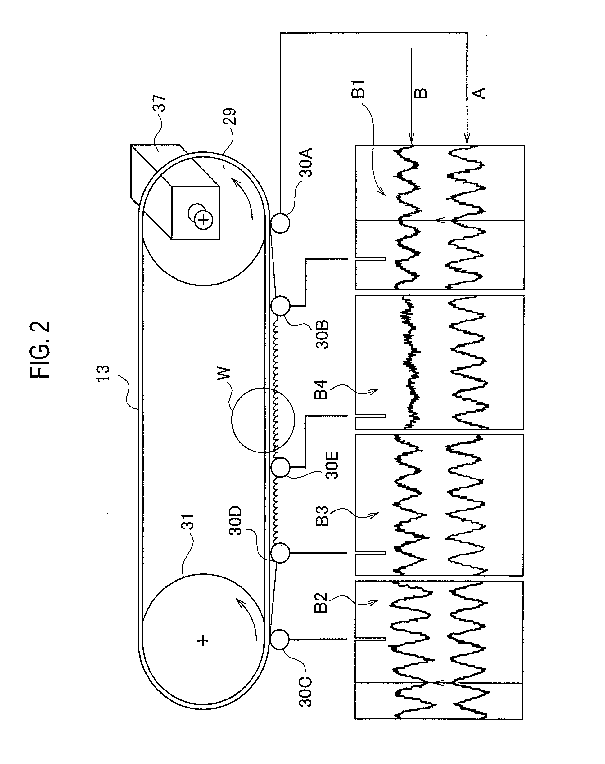
[0050]As shown in FIG. 2, the configuration shown in FIG. 2 includes forced oscillation imparting means which imparts to the band saw blade 13 a forced longitudinal oscillation so that the phase of the oscillation which occurs to the band saw blade 13 in a main-component-force direction (in its rotational direction, in its running direction) (that is, the oscillation which occurs to the band saw blade 13 in its rotational direction or in its running direction, and which is a longitudinal or compressional oscillation) near the driving wheel 29 is substantially inverted to the phase of the oscillation which occurs to the band saw blade 13 in a main-component-force direction near the driven wheel 31. In other word...


PUM

PropertyMeasurementUnit
Phaseaaaaaaaaaa

Abstract

A method of cutting a workpiece using an endless band saw blade and a band saw machine are provided. The method includes suspending the endless band saw blade between a driving wheel and a driven wheel such that the workpiece may be cut by the endless band saw blade, applying at least a first pulse and a second pulse to a first motor rotating the driving wheel and a second motor rotating the driven wheel, respectively, wherein the pulses have phases opposite to each other, and cutting the workpiece. The band saw machine includes an endless band saw blade suspended between a driving wheel having a first motor and a driven wheel having a second motor. The band saw machine further includes a pulse applying module that applies at least a first pulse and a second pulse to the first motor and the second motor, respectively, wherein the pulses have phases opposite to each.

Description

CROSS-REFERENCE TO RELATED APPLICATION[0001]The present application is a continuation application based on pending U.S. patent application Ser. No. 11 / 915,266 filed on Nov. 21, 2007 (national stage application of PCT / JP2006 / 310265, filed May 23, 2006), which claims priority based upon Japanese Application Nos. JP2005-150053, filed May 25, 2005, JP2006-005128, filed Jan. 12, 2006, JP2006-050617, filed Feb. 27, 2006, and JP2006-050704, filed Feb. 27, 2006, the contents of which are expressly incorporated by reference herein in their entirety.TECHNICAL FIELD[0002]The present invention relates to a method of cutting off a workpiece using a band saw machine including a band saw blade, and to a band saw machine used for the cutting-off method. More specifically, the present invention relates to a method of cutting off a workpiece while restraining a band saw blade from chattering, and to the band saw machine used for the cutting-off method.BACKGROUND ART[0003]Band saw machines include ver...

Claims


Application Information

Patent Timeline
IPC IPC(8): B27B13/00B26D1/00
CPCB23D55/005B26D1/46B23D59/001B23D55/06Y10T83/04Y10T83/0605Y10T83/141Y10T83/148Y10T83/707Y10T83/7139B23D55/00
Inventor TOKIWA, TORU
Owner AMADA CO LTD
Why Eureka
Try Eureka