Method and device for manufacturing bolt, screw rolling die used therefor, and multiple screw bolt

a manufacturing method and technology of screw rolling die, applied in threaded fasteners, forging/pressing/hammering apparatuses, forging/hammering/pressing machines, etc., can solve the problems of inability to form both coarse and fine threads on a single die integrally, and inability to manufacture double screw bolts. , to achieve the effect of suppressing chatter vibration, reducing the variation of the diameter of the rolling pitch

Active Publication Date: 2006-10-12
FORM ROLL TECH
View PDF4 Cites 19 Cited by
  • Summary
  • Abstract
  • Description
  • Claims
  • Application Information

AI Technical Summary

Benefits of technology

[0025] (1) There is provided at least one thread rolling die that has: part of a coarse thread formed by developing a coarse screw; and part of a fine thread formed by developing a fine screw, the fine thread being formed cyclically on a root portion of the coarse thread according to a phase shift between the fine screw and the coarse screw. A bolt material is pressed and rolled against the thread rolling die. With this configuration, the bolt material is pressed by the part of the coarse thread and the part of the fine thread formed on the thread rolling die, so that the part of the coarse thread and the part of the fine thread are transferred to the peripheral surface of this bolt material in a single step at a time. This makes it possible to mass-produce a bolt having so-called double screws, provided with the part of the coarse thread and the part of the fine thread, at a unit price lower than by cutting.
[0026] (2) There is provided at least one thread rolling die that has: part of a coarse thread formed by developing a coarse screw; and part of a fine thread which appears cyclically on a root portion of this coarse thread at every (b) turns of the coarse thread according to a phase shift from the coarse thread when a fine screw having a helical line in the same direction as that of the coarse screw and a pitch smaller than that of the coarse screw (where the ratio between the pitches of the coarse screw and the fine screw is (a) to (b); (a) and (b) are in a minimum integer ratio) is developed. A bolt material is pressed and rolled against the thread rolling die. With this configuration, the bolt material is pressed by the part of the coarse thread and the part of the fine thread formed on the thread rolling die, so that the part of the coarse thread and the part of the fine thread are transferred to the peripheral surface of this bolt material in a single step at a time. This makes it possible to mass-produce a so-called double screw bolt, provided with the part of the coarse thread and the part of the fine thread, at a unit price lower than by cutting.
[0027] (3) There is provided at least one thread rolling die that further has part of a finest thread which appears cyclically on a root portion formed by the part of the coarse thread and the part of the fine thread at every (c) turns of the coarse thread according to phase shifts from the part of the coarse thread and the part of the fine thread when a finest screw having a helical line in the same direction as that of the coarse screw and a pitch even smaller than that of the fine screw (where the ratios among the pitches of the coarse screw, the fine screw, and the finest screw are (a) to (b) to (c); (a), (b) and (c) are in minimum integer ratios) is developed. A bolt material is pressed and rolled against the thread rolling die. With this configuration, the bolt material is pressed by the part of the coarse thread, the part of the fine thread, and the part of the finest thread formed on the thread rolling die, so that the part of the coarse thread, the part of the fine thread, and the part of the finest thread are transferred to the peripheral surface of this bolt material in a single step at a time. This makes it possible to mass-produce a so-called triple screw bolt, provided with the part of the coarse thread, the part of the fine thread, and the part of the finest thread, at a unit price lower than by cutting.
[0028] (4) There is provided at least one thread rolling die that has: part of a coarse thread formed by developing a coarse screw; and part of each of fine threads which appear cyclically on a root portion of this coarse thread at every (n) turns of the coarse thread according to phase shifts from the coarse thread when one or a plurality of fine screws having helical lines in the same direction as that of the coarse screw and respective different pitches smaller than that of the coarse screw (where the ratios among the pitches of the coarse screw and the plurality of fine screws are (a) to . . . to (n); (a), . . . , and (n) are in minimum integer ratios) are developed, respectively. A bolt material is pressed and rolled against the thread rolling die. With this configuration, the bolt material is pressed by the part of the coarse thread and the part of the plurality of fine threads formed on the thread rolling die, so that the part of the coarse thread and the part of each of the plurality of fine threads are transferred to the peripheral surface of this bolt material in a single step at a time. This makes it possible to mass-produce a so-called multiple screw bolt, provided with the part of the coarse thread and the part of each of the plurality of fine threads, at a unit price lower than by cutting.
[0029] (5) The part of the fine thread having the smallest pitch among the fine threads appears cyclically at every (n) turns of the coarse thread according to a phase shift from the coarse thread when the fine screw is developed so that the root of the fine screw developed lies in a position higher than the root of the coarse thread. At the time of rolling, this decreases variations of the rolling pitch circle diameter in the final phase of machining, thereby reducing fluctuations in the position of the rotation center of the bolt material. The material filling factors to groove portions of the thread rolling die thus become more uniform, allowing significant suppression of chatter vibrations.
[0030] (6) The thread rolling die has a deep groove further into the root of the part of the fine thread. This makes it possible to manufacture a multiple screw bolt that has a fine thread having the same height as that of the fine thread of the thread rolling die even if the groove portions of the thread rolling die are not filled with the bolt material completely during the rolling of the multiple screw bolt. In addition, the incomplete fill can suppress chatter vibrations in the final phase of machining, which occur from such factors as complete fill.

Problems solved by technology

Besides, when the coarse screw portion formed by the first cutting is subjected again to the second cutting to form the fine screw portion, the areas cut twice can cause burrs.
Nevertheless, even if a coarse die and a fine die are arranged opposite to each other across a certain interval and a bolt shank is put and rolled between the coarse die and fine die as described in the patent document 1, it is actually impossible to manufacture a double screw bolt.
While the expression of a die having both a coarse thread and a fine thread is seemingly correct, it is in fact impossible to form both a coarse thread and a fine thread on a single die integrally.
Based on the description of the patent document 1 alone, it is thus impossible to manufacture the double screw bolt.
Since the cutting-based manufacturing method as described above includes a greater number of manufacturing steps than for ordinary bolts, however, the cost of manufacturing is extremely high and the double screw bolt comes at a very high unit price.

Method used


Image

  • Method and device for manufacturing bolt, screw rolling die used therefor, and multiple screw bolt
  • Method and device for manufacturing bolt, screw rolling die used therefor, and multiple screw bolt
  • Method and device for manufacturing bolt, screw rolling die used therefor, and multiple screw bolt

Examples


embodiment 1

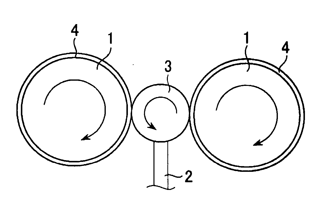
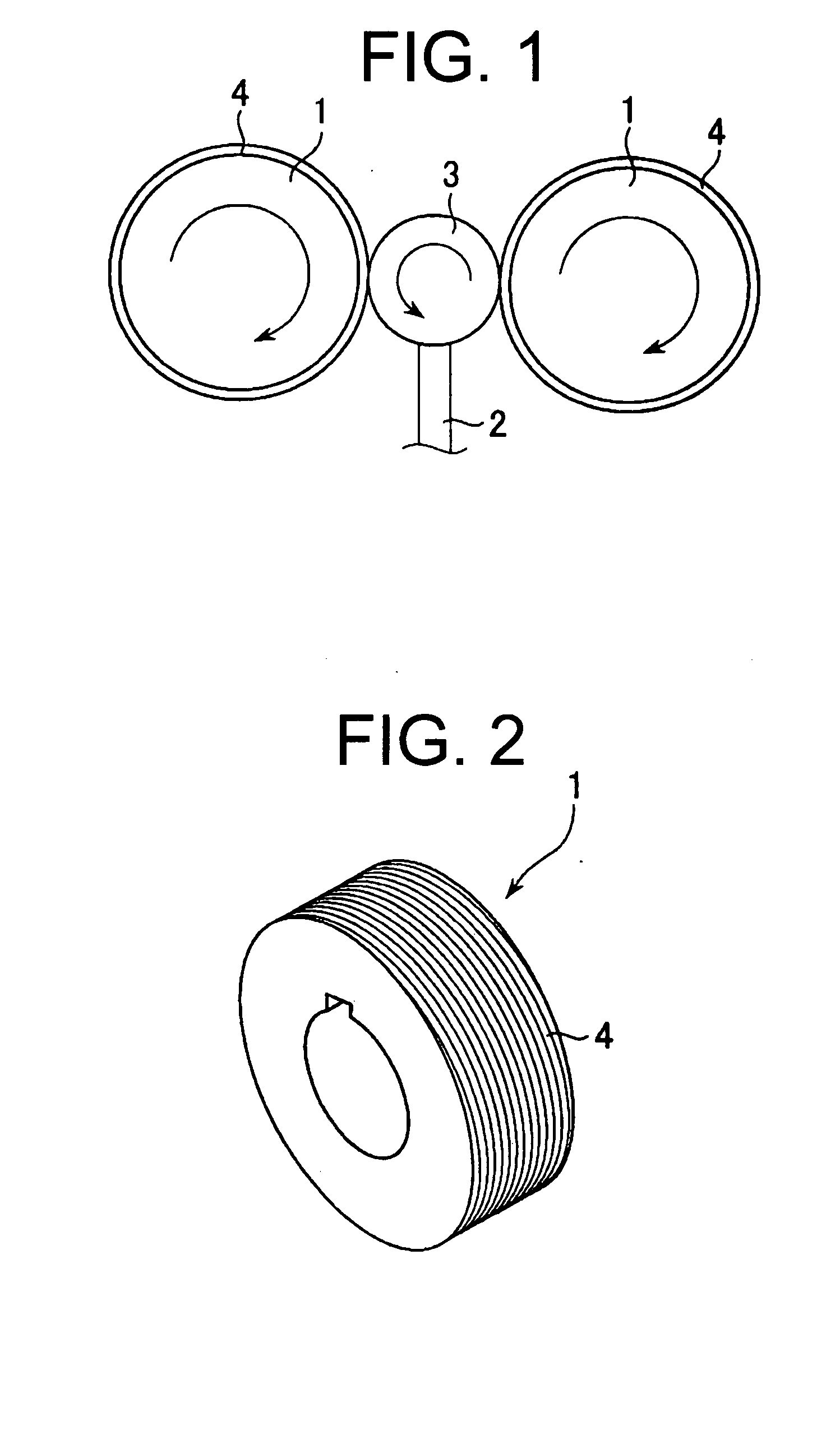
[0033]FIG. 1 is a schematic diagram showing an apparatus for manufacturing a double screw bolt according to a first embodiment of the present invention. FIG. 2 is a perspective view showing a thread rolling die 1 of FIG. 1.

[0034] As shown in FIG. 1, the apparatus for manufacturing a double screw bolt according to the present embodiment comprises a pair of the thread rolling dies 1 which are arranged opposite to each other at a predetermined interval, and a bolt supporting unit 2 which supports a cylindrical bolt material (hereinafter, referred to as “work”) 3 in a predetermined position. As shown in FIG. 2, the thread rolling dies 1 are dies of cylindrical shape (cylindrical dies) on the peripheries of which a transfer pattern 4 for forming a double screw bolt is formed.

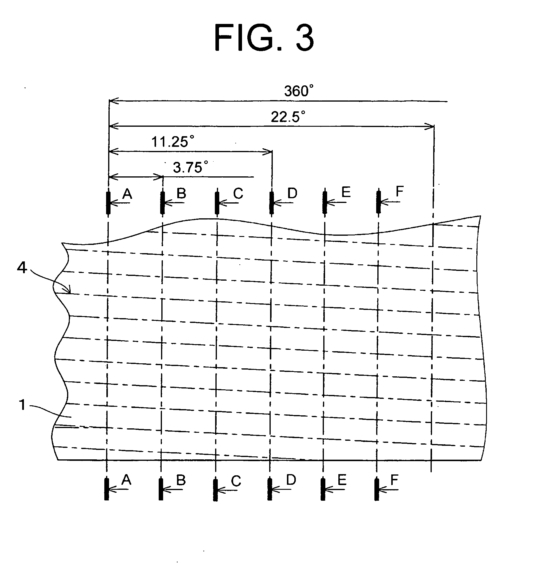
[0035]FIG. 3 is a diagram showing part of the transfer pattern 4 on the periphery of the thread rolling die 1 of FIG. 2, developed on a plane. FIGS. 4A, 4B, 4C, 4D, 4E, and 4F are sectional views taken along the li...

embodiment 2

[0054]FIG. 9 is a schematic diagram showing the apparatus for manufacturing a double screw bolt according to a second embodiment of the present invention.

[0055] As shown in FIG. 9, the apparatus for manufacturing a double screw bolt according to the present embodiment has a pair of thread rolling dies 8 which are opposed to each other at a predetermined interval. One of the pair of thread rolling dies 8 is fixed and the other is arranged to be capable of parallel movement, or both are arranged to be capable of parallel movement in opposite directions.

[0056] The thread rolling dies 8 are plate-like dies (flat dies) having a transfer pattern 9 for forming a double screw bolt on one side. The transfer pattern 9 is one identical to the transfer pattern 4 according to the first embodiment, developed on a plane.

[0057] To manufacture a double screw bolt by using this apparatus for manufacturing a double screw bolt, a cylindrical work 3 is pressed between the pair of thread rolling dies ...

embodiment 3

[0058]FIGS. 10A, 10B, 10C, 10D, 10E, and 10F are sectional views of a thread rolling die 10 for a triple screw bolt according to a third embodiment of the present invention. A transfer pattern corresponding to the triple screw bolt to manufacture is formed to repeat 16 times per round on the periphery of the thread rolling die 10. FIGS. 10A to 10F are diagrams showing cross-sections of the periphery of the thread rolling die 10 at intervals of 3.75 degrees.

[0059] As shown in FIGS. 10A to 10F, the thread rolling die 10 for a triple screw bolt further has projections 12 that are made of part of a finest thread (shown by a dashed line (imaginary line) 12a in FIGS. 10A to 10F) which appears cyclically on root portions 11 formed by the coarse thread portion 5 and the projections 6 at every (c) turns (in the shown example, each single turn) of the coarse thread according to phase shifts from the coarse screw portion 5 and the projections 6 when a finest screw having a helical line in the...


PUM

PropertyMeasurementUnit
diameteraaaaaaaaaa
diameteraaaaaaaaaa
distanceaaaaaaaaaa

Abstract

A method and apparatus for manufacturing a bolt capable of mass-producing a multiple screw bolt such as a so-called double screw bolt at a low unit price, and a thread rolling die for use therein. The apparatus for manufacturing a bolt comprises a pair of thread rolling dies (1) which are arranged opposite to each other at a predetermined interval, and a bolt supporting unit (2) which supports a cylindrical bolt material (3) in a predetermined position. The thread rolling dies (1) are provided with a transfer pattern (4) having a coarse thread portion (5) which is part of a coarse thread formed by developing a coarse screw, and projections (6) which are part of a fine thread (6a) formed by developing a fine screw as shown by an imaginary line (6a), the fine thread (6a) being formed cyclically on a root portion (5a) of the coarse thread according to a phase shift between the fine thread and the coarse thread.

Description

TECHNICAL FIELD [0001] The present invention relates to a method and apparatus for manufacturing a bolt having an anti-loosening function, a thread rolling die for use therein, and a multiple screw bolt. BACKGROUND ART [0002] In recent years, research and development have been conducted on various types of bolts having anti-loosening functions and methods of manufacturing the same. For example, International Publication Pamphlet No. 02 / 077466 (hereinafter, referred to as “patent document 1”) describes a bolt which comprises a coarse screw portion having a pitch of P, formed from the extremity to a predetermined part of the bolt shank, and a fine screw portion having a pitch of p (p=P / n; n is an integer no smaller than 2), formed at least over the entire length of the coarse screw portion of the bolt shank or so as to overlap with the coarse screw portion from the extremity to a predetermined part of the coarse screw portion. [0003] With this bolt (so-called double screw bolt), a coa...

Claims


Application Information

Patent Timeline
Patent Type & Authority Applications(United States)
IPC IPC(8): B21H3/04B21H3/06B21H3/02
CPCB21H3/02B21H3/06B21H3/042B21H3/04
Inventor TAKEMASU, TERUIEMIYAHARA, HIROSHI
Owner FORM ROLL TECH
Why Eureka
Try Eureka