
System for creating an air-to-ground IP tunnel in an airborne wireless cellular network to differentiate individual passengers

a wireless cellular network and air-to-ground technology, applied in the field of cell communication, can solve the problem that the communication cannot be individually identified by the ground-based access network, and achieve the effect of simplifying the provision of these services and enhancing the travel experience of passengers

Inactive Publication Date: 2009-01-08
GOGO BUSINESS AVIATION LLC
View PDF13 Cites 69 Cited by
  • Summary
  • Abstract
  • Description
  • Claims
  • Application Information

AI Technical Summary

Benefits of technology

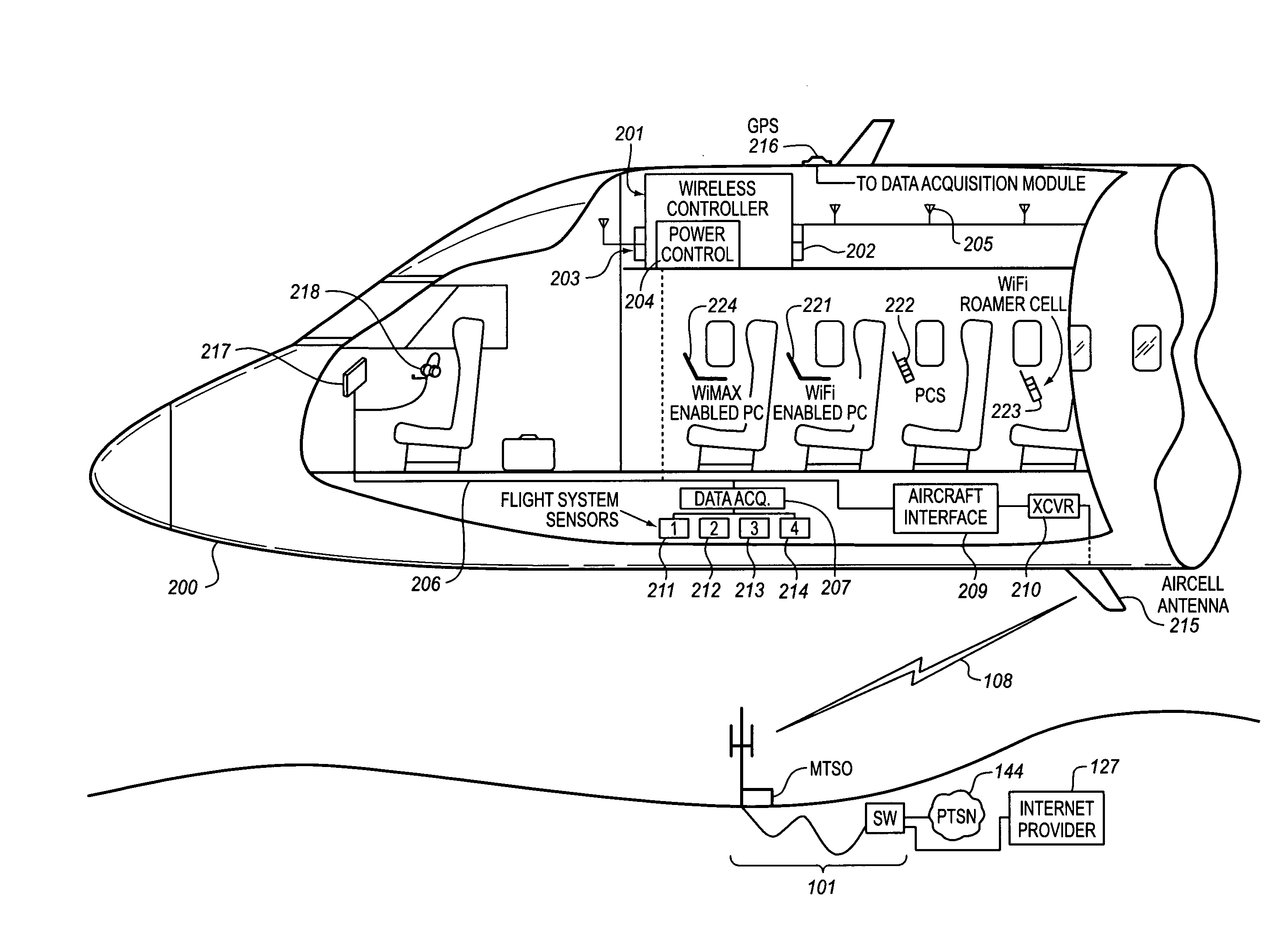
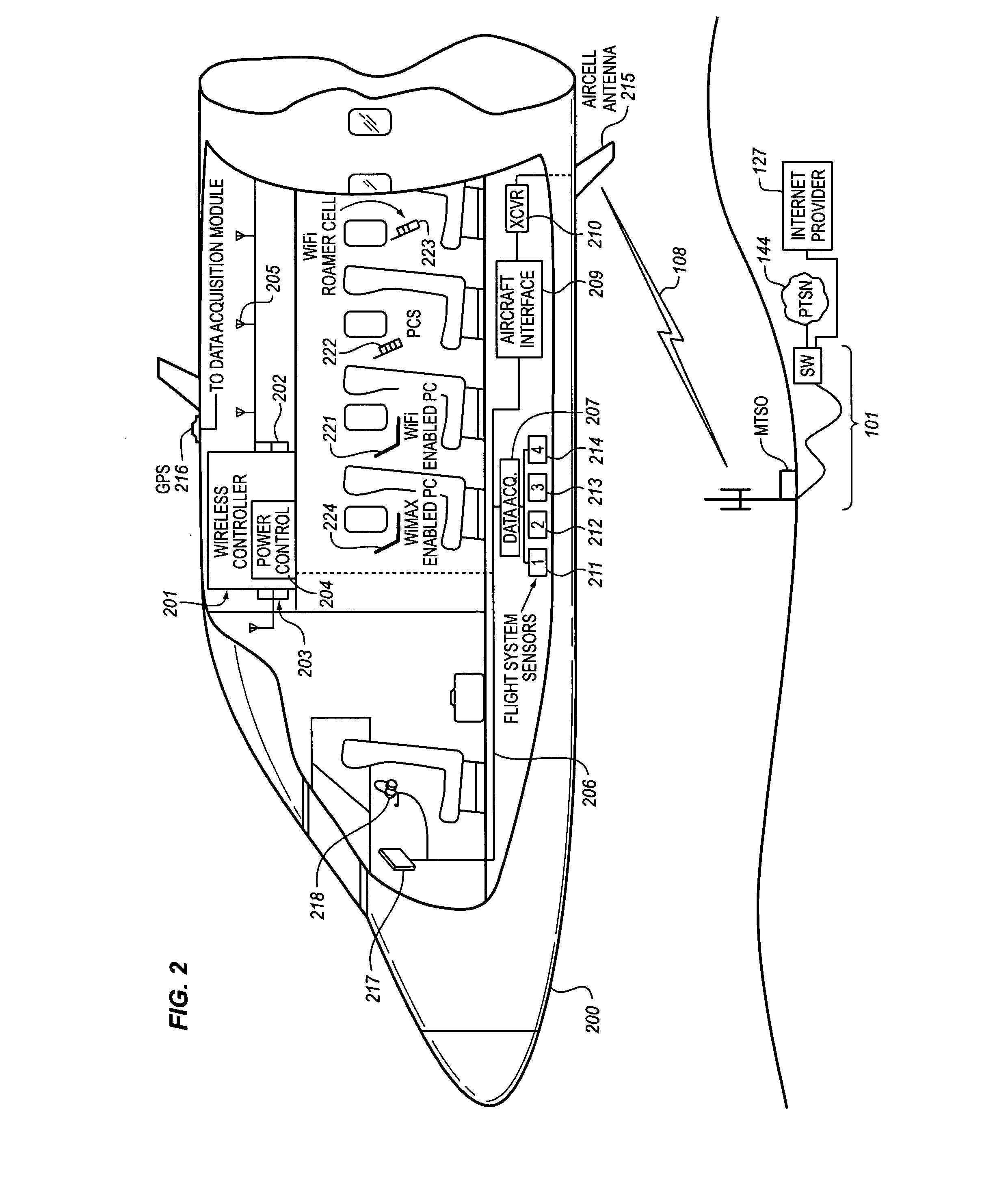
[0008]The Aircraft Air-To-Ground IP Tunnel System provides wireless communication services to passengers who are located onboard an aircraft by storing data indicative of the individually identified passenger wireless devices that are located onboard the aircraft. The Aircraft Air-To-Ground IP Tunnel System assigns a single IP address to each Point-to-Point Protocol radio frequency link which connects the aircraft network to the ground-based Access Network, but also creates an IP Tunnel from the ground-based Access Network to the aircraft. The IP Tunnel supports a plurality of IP addresses for the passenger wireless devices served by each of the Air-To-Ground radio frequency links thereby to enable each passenger wireless device to be uniquely identified with their own IP address. The NAT onboard the aircraft can utilize a greater number of IP addresses than one per link by the use of the Aircraft Air-To-Ground IP Tunnel System. Such an approach does not change IPCP or other EVDO protocols / messaging but does allow the passenger wireless device individual IP address to be directly visible to the ground-based Access Network.
[0009]The electronic services that are provided to the passenger include Internet, in-flight entertainment services, such as multi-media presentations, as well as destination-based services, which link the passenger's existing travel plans with offers for additional services that are available to the passenger at their nominal destination and their planned travel schedule, and optionally, voice services. The passenger thereby is presented with opportunities during their flight to enhance their travel experience, both in-flight and at their destination, by accessing the various services. The individual identification of each passenger wireless device simplifies the provision of these services and enables the customization of these services based upon predefined profiles created for the passenger.
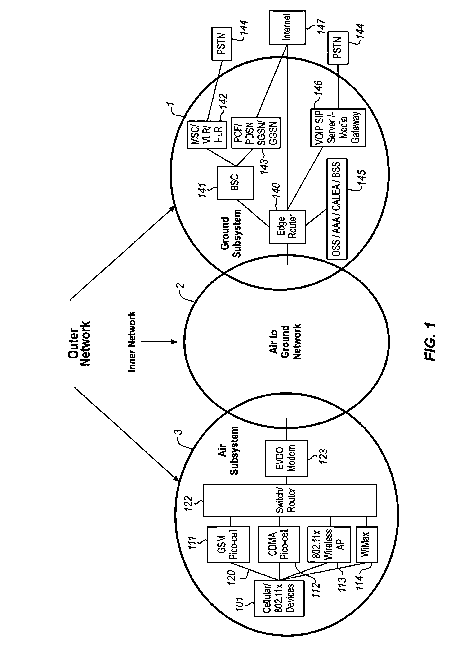
[0010]This provision of the Aircraft Air-To-Ground IP Tunnel System is accomplished in part by the use of an “Inner Network” that connects the two segments of the “Outer Network”, comprising the Air Subsystem and the ground-based Access Network. The Inner Network transmits both the subscriber traffic (comprising voice and / or other data) and feature set data between the Air Subsystem and the ground-based Access Network thereby to enable the passenger wireless devices that are located in the aircraft to receive consistent wireless communication services in both the terrestrial ground-based) and non-terrestrial regions.

Problems solved by technology

It is a problem in the field of wireless communications to manage the wireless services provided by an aircraft network to passengers who are located in the aircraft as they roam among cell sites in the non-terrestrial cellular communication network.
Thus, the wide bandwidth radio frequency connection concurrently carries the communications of multiple individual passengers, but these communications cannot be individually identified by the ground-based Access Network.

Method used


Image

  • System for creating an air-to-ground IP tunnel in an airborne wireless cellular network to differentiate individual passengers
  • System for creating an air-to-ground IP tunnel in an airborne wireless cellular network to differentiate individual passengers
  • System for creating an air-to-ground IP tunnel in an airborne wireless cellular network to differentiate individual passengers

Examples


Embodiment Construction

Overall System Architecture

[0019]FIG. 1 illustrates, in block diagram form, the overall architecture of the non-terrestrial cellular communication network, which includes an Air-To-Ground Network 2 (Inner Network) that interconnects the two elements of an Outer Network, comprising an Air Subsystem 3 and Ground Subsystem 1. This diagram illustrates the basic concepts of the non-terrestrial cellular communication network and, for the purpose of simplicity of illustration, does not comprise all of the elements found in a typical non-terrestrial cellular communication network. The fundamental elements disclosed in FIG. 1 provide a teaching of the interrelationship of the various elements which are used to implement a non-terrestrial cellular communication network to provide content to passenger wireless devices which are located in an aircraft.

[0020]The overall concept illustrated in FIG. 1 is the provision of an “Inner Network” that connects the two segments of the “Outer Network”, com...


PUM


Abstract

The Aircraft Air-To-Ground IP Tunnel System provides wireless communication services to passengers located onboard an aircraft by storing data indicative of the individually identified passenger wireless devices located onboard the aircraft. The Aircraft Air-To-Ground IP Tunnel System assigns a single IP address to each Point-to-Point Protocol link connecting the aircraft network to the ground-based communication network and creates an IP subnet onboard the aircraft. The IP subnet utilizes a plurality of IP addresses for each Point-to-Point link, enabling each passenger wireless device to be uniquely identified with their own IP address. This is enabled since both Point-to-Point Protocol IPCP endpoints have pre-defined IP address pools and / or topology configured, so each Point-to-Point Protocol endpoint can utilize a greater number of IP addresses than one per link. Such an approach does not change IPCP or other EVDO protocols / messaging but allows this address to be directly visible to the ground-based communication network.

Description

CROSS-REFERENCE TO RELATED APPLICATIONS[0001]This application is a continuation-in-part of U.S. patent application Ser. No. 11 / 492,545 filed Jul. 24, 2006; which is a continuation of U.S. patent application Ser. No. 10 / 730,329 filed Dec. 7, 2003, now U.S. Pat. No. 7,113,780 issued Sep. 26, 2006; which is a continuation-in-part of U.S. patent application Ser. No. 09 / 686,923 filed Oct. 11, 2000, now U.S. Pat. No. 6,788,935 issued Sep. 7, 2004. This application is also related to U.S. patent application titled “System For Creating An Aircraft-Based Internet Protocol Subnet In An Airborne Wireless Cellular Network” and filed on the same date as the present application. This application is also related to U.S. patent application titled “System For Managing Mobile Internet Protocol Addresses In An Airborne Wireless Cellular Network” and filed on the same date as the present application.FIELD OF THE INVENTION[0002]This invention relates to cellular communications and, in particular, to a s...

Claims


Application Information

Patent Timeline
Patent Type & Authority Applications(United States)
IPC IPC(8): H04B7/185
CPCH04B7/18506H04B7/18508H04W16/24H04W36/08H04W84/06H04W80/04H04W84/005H04W84/042H04W76/02H04W76/10H04W36/083
Inventor LAUER, BRYAN A.STAMATOPOULOS, JERRYRASHID, ANJUMTOBIN, JOSEPH A.WALSH, PATRICK J.ARNTZEN, STEVEN J.
Owner GOGO BUSINESS AVIATION LLC
Learn More