Universal Modular Stent Graft Assembly to Accommodate Flow to Collateral Branches

a modular, stent technology, applied in the field of arterial disease treatment, can solve the problems of cumbersome and difficult operation, laborious and expensive production, and inability to obtain the exact measurements required to build the custom stented graft structure, and achieve the effect of reducing labor costs

Active Publication Date: 2009-01-08
MEDTRONIC VASCULAR INC
View PDF14 Cites 48 Cited by
  • Summary
  • Abstract
  • Description
  • Claims
  • Application Information

AI Technical Summary

Benefits of technology

[0020]As discussed above, the longitudinal dimension, or length, of the collateral openings of the universal modular stented graft assemblies of the invention is adjustable and the longitudinal positioning of the openings is also adjustable. In addition, the radial dimension, or width, of the collateral openings of the universal modular stented graft assemblies of the invention is also adjustable, as is the radial positioning of the collateral openings. Consequently, in contrast to prior art methods and structures, the universal modular stented graft assemblies of the invention do not need to be custom made for each patient. Therefore, the universal modular stented graft assemblies of the invention can be mass-produced with minimal labor costs and kept in inventory on site until needed.
[0021]In addition, using the universal modular stented graft assemblies of the invention, it not necessary to obtain the exact measurements that were required to build the custom stented graft structures used with prior art techniques. Consequently, there is less opportunity to introduce human error in both the measurement taking process and the implementing of those measurements during production / assembly / deployment.

Problems solved by technology

A more severe problem occurs when it is desirable to use a graft or a stented graft at or around the intersection of a major artery (e.g., the aorta) with intersecting collateral arteries (e.g., the renal arteries).
The Taheri 878 and Evans et al. prior art techniques discussed above, while somewhat effective, were cumbersome and difficult to employ and execute.
Consequently, the custom stented graft structures used with prior art techniques such as Taheri '824 were, of course, not subject to mass production and were very labor intensive and expensive to produce.
Another drawback to the custom stented graft structures used with prior art techniques was that it was not always possible to obtain the exact measurements required to build the custom stented graft structures used because, even with modern imaging technology, it is not always possible to see, and precisely measure, every location in the human body.
To complicate matters further, even if the exact measurements were, in theory, available, there was significant opportunity for the introduction of error in both the measurement taking process and the implementation of those measurements in the production of the custom stented graft structure.
In addition, because the custom stented graft structures used with prior art techniques were custom made, there was considerable time lag between diagnosis and deployment of the stented graft structure while waiting for the custom stented graft structure to be built.
In addition, since the stented graft structures used with prior art techniques were custom made, the delivery and deployment mechanisms were also variable and subject to error and unanticipated complications.
In short, custom stented graft structures used with the prior art required precise measurement and production techniques, were vulnerable to error, and had to be special ordered well in advance of their use.
Consequently, the custom stented graft structures used with the prior art were far from ideal and had significant limitations.

Method used


Image

  • Universal Modular Stent Graft Assembly to Accommodate Flow to Collateral Branches
  • Universal Modular Stent Graft Assembly to Accommodate Flow to Collateral Branches
  • Universal Modular Stent Graft Assembly to Accommodate Flow to Collateral Branches

Examples


Embodiment Construction

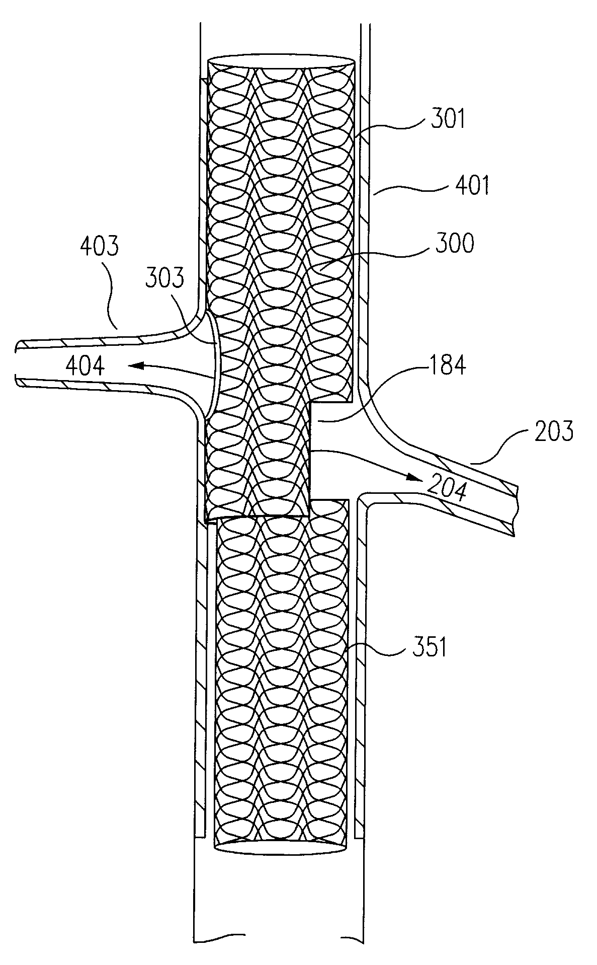
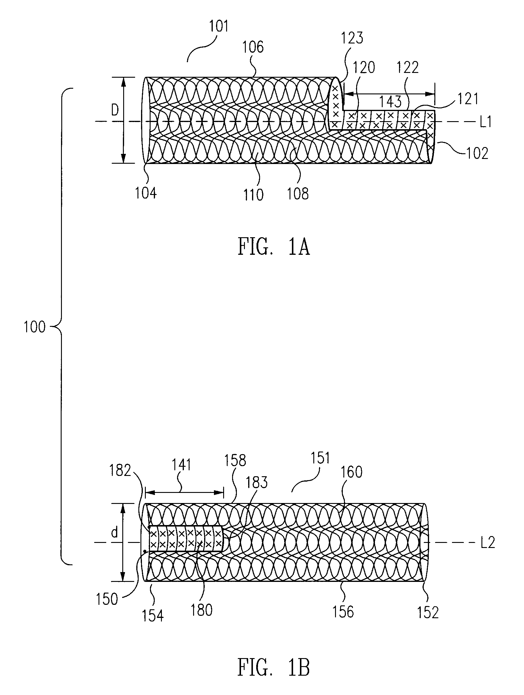
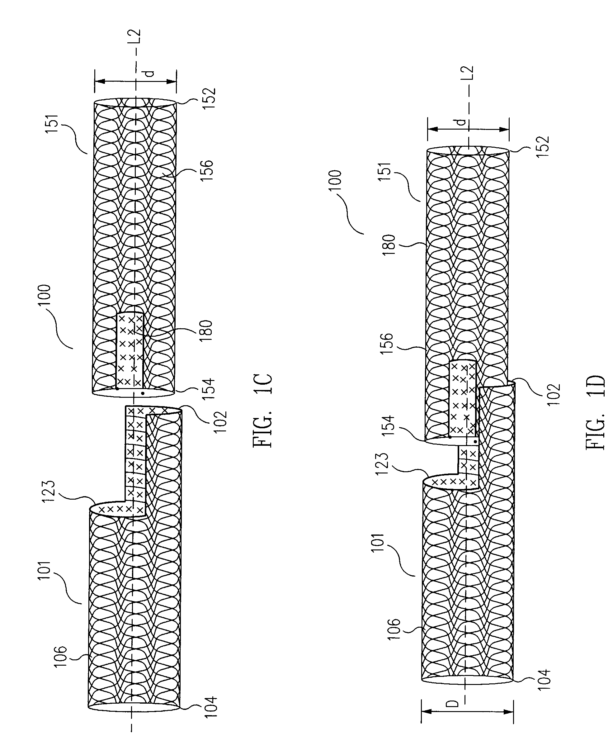
[0050]In embodiments in accordance with the principles of the present invention, universal modular stented graft assemblies (100 in FIGS. 1A to 1K and 2A, 2B, 300 in FIGS. 3A to 3C and 4, 500 in FIG. 5A to 5C, 600 in FIGS. 6A to 6C) are assembled (FIGS. 1C to 1I), on site, i.e. at the hospital or in the operating room, and often in a patient's parent artery (201 in FIGS. 2A and 2B, 401 in FIG. 4), from at least two components; a first component (101 in FIGS. 1A to 1K and 2A to 2B, 301 in FIGS. 3A to 3C and 4, 501 in FIGS. 5A to 5C, 601 in FIGS. 6A to 6C) and a second component (151 in FIGS. 1A to 1K and 2A to 2B, 351 in FIGS. 3A to 3C and 4, 551 in FIGS. 5A to 5C, 651 in FIGS. 6A to 6C). The first and second components each include a window, or fenestration (120 and 180 in FIGS. 1A to 1K and 2A to 2B, 620 and 680 in FIGS. 6A to 6C). In one example, the second component has a diameter (d in FIG. 1B) usually slightly smaller than the diameter (D in FIG. 1A) of the first component so t...


PUM


Abstract

Universal modular stented graft assemblies are assembled, on site, and often in a patient's parent artery, from at least two components; a first component and a second component. The first and second components each include a window, or fenestration. The second component couples with the first component by fitting at least partially in the first component to form the universal modular stent graft assembly with an adjustable collateral opening. As the first and second components are assembled, the first and second components are adjusted relative to each other so that the first and second component windows overlap to form a collateral opening whose size is selectable, depending on the overlap, with the desired position and dimensions in the universal modular stent graft assembly.

Description

BACKGROUND OF THE INVENTION[0001]1. Field of the Invention[0002]The present invention relates generally to the treatment of arterial disease, including for example, aortic occlusive disease, and in particular, to a universal modular stent graft assembly and method for treating arterial disease at the intersection of two or more arteries or blood flow passageways such as the intersection of the aorta and renal arteries or the aorta and posterior spinal arteries[0003]2. Description of the Related Art[0004]In the prior art, treatment of arterial disease was effected by various surgical techniques, some of which involved the use of stents and grafts. For example, it is well known in the art to interpose within the diseased portion of an artery a stent, whether made of stainless steel, nitinol or other materials capable of being balloon-expanded or self-expanded, for strengthening the walls of a stenotic or occluded artery. Grafts, comprised of hollow tubes of material such as Dacron, we...

Claims


Application Information

Patent Timeline
Patent Type & Authority Applications(United States)
IPC IPC(8): A61F2/06A61F2/00A61F2/82A61F2/90
CPCA61F2/07A61F2/852A61F2/856A61F2/90A61F2002/061A61F2250/0008A61F2250/006A61F2250/0065A61F2002/075A61F2220/0033A61F2002/826
Inventor DOIG, SCOTTMACHEK, JAMES
Owner MEDTRONIC VASCULAR INC
Why Eureka
Try Eureka