Laminated Moulded Parts and Manufacture Thereof

a technology of laminated parts and manufacturing methods, applied in the direction of layered products, synthetic resin layered products, chemistry apparatus and processes, etc., can solve the problems of poor finish in the final lacquer coating of components, difficult control of moulding process, and difficult production of press-moulded net shape moulded parts from composite materials, etc., to achieve fast cure, high quality, and high quality a surface

Inactive Publication Date: 2017-11-23
GURIT (UK) LTD
View PDF2 Cites 0 Cited by
  • Summary
  • Abstract
  • Description
  • Claims
  • Application Information

AI Technical Summary

Benefits of technology

[0013]The preferred embodiments of the present invention can provide the assembly of a net shaped preform in a mould, and then the preform is transferred to a press mould for press moulding. The use of press moulding allows a faster cure for the thermosetting resin than conventional autoclave processing which is used for the manufacture of composite material parts having a high quality surface finish as the press can be kept hot at the required cure temperature whereas in autoclave processing the tool is cycled between a relatively cool lay-up and a relatively hot cure temperature.
[0014]The preferred embodiments of the present invention can provide a net shaped preform which, after press moulding, exhibits in the final moulded part a high quality A surface, and also a high quality B surface. The moulded part has a smoothly rounded, beaded edge that just needs de-flashing (rather than machining) before coating with a clear lacquer finish coat.
[0015]The preferred embodiments of the present invention can enable the use of simple press mould tooling with a bulb feature to give a beaded edge feature without the need to have sliding tool parts to de-mould the component. This gives the advantage of a sealed and cosmetic pleasing edge which is safe to handle, and has enhanced stiffness and strength. The sealed moulded edge reduces moisture ingress into the laminate as compared to a machined edge, and that sealing can reduce the risk of delaminating the lacquer coating applied to the moulded part to finish the component.
[0016]The provision of a net-shaped preform with a beaded edge which is then press moulded improves the surface properties, particularly at the “A-surface” which is, in use, the front face of the moulded part.
[0017]The press moulding method of the invention may be employed to produce high volume, lightweight, low cost automotive body panels composed of composite material, and such production may incur minimal labour costs as a result of reducing or avoiding post-moulding finishing costs since the resin flash is minimised or eliminated and the part is accurately moulded.
[0018]The resin composition may be selected to have a high degree of cross-linking, so as to have a high glass transition temperature Tg, with the result that the moulded part is able to be conveyed along a high temperature paint line without distortion or surface damage to maintain what is categorised for automotive body panels by those skilled in the art as a “class A” surface finish.

Problems solved by technology

A particular problem encountered with press moulding of an initial charge, or preform, of moulding material which at least partially comprises prepreg and / or SMC components, is that due to manufacturing tolerances in the initial charge the volume of the mould cavity is not always equal to the volume of the initial charge.
Consequently, it is difficult to control the moulding process, especially to produce a composite material part having a moulded shape and dimensions which, on exit from the mould, have very close tolerance to the desired final shape and dimensions of the ultimately manufactured part, i.e. a “net shape moulded part”.
This problem is particularly acute when the moulded part has fine edge details, not only because fine shape and dimensions need to be accurately moulded but also because exposed edges of the composite material must be sealed with resin, so that the fibres are not exposed, in order to avoid cosmetic or structural defects occurring during subsequent manufacturing steps or during use of the moulded part.
Currently, using known composite material moulding technology, it is difficult to produce a press-moulded net shape moulded part from a composite material which does not require to be machined, trimmed or re-worked after moulding.
Autoclave processing has been used for the manufacture of these parts, in preference to vacuum bag curing, because the higher autoclave pressure during resin impregnation and curing reduces the tendency for resin voids and pin-hole defects in the surface, resulting in a poor finish in the final lacquer coated components.
VARTM / RTM type processes are less preferred due to the tendency to distort fabrics during lay-up and the resin injection disturbing and distorting the woven finish.

Method used


Image

  • Laminated Moulded Parts and Manufacture Thereof
  • Laminated Moulded Parts and Manufacture Thereof
  • Laminated Moulded Parts and Manufacture Thereof

Examples


example 1

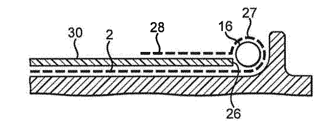
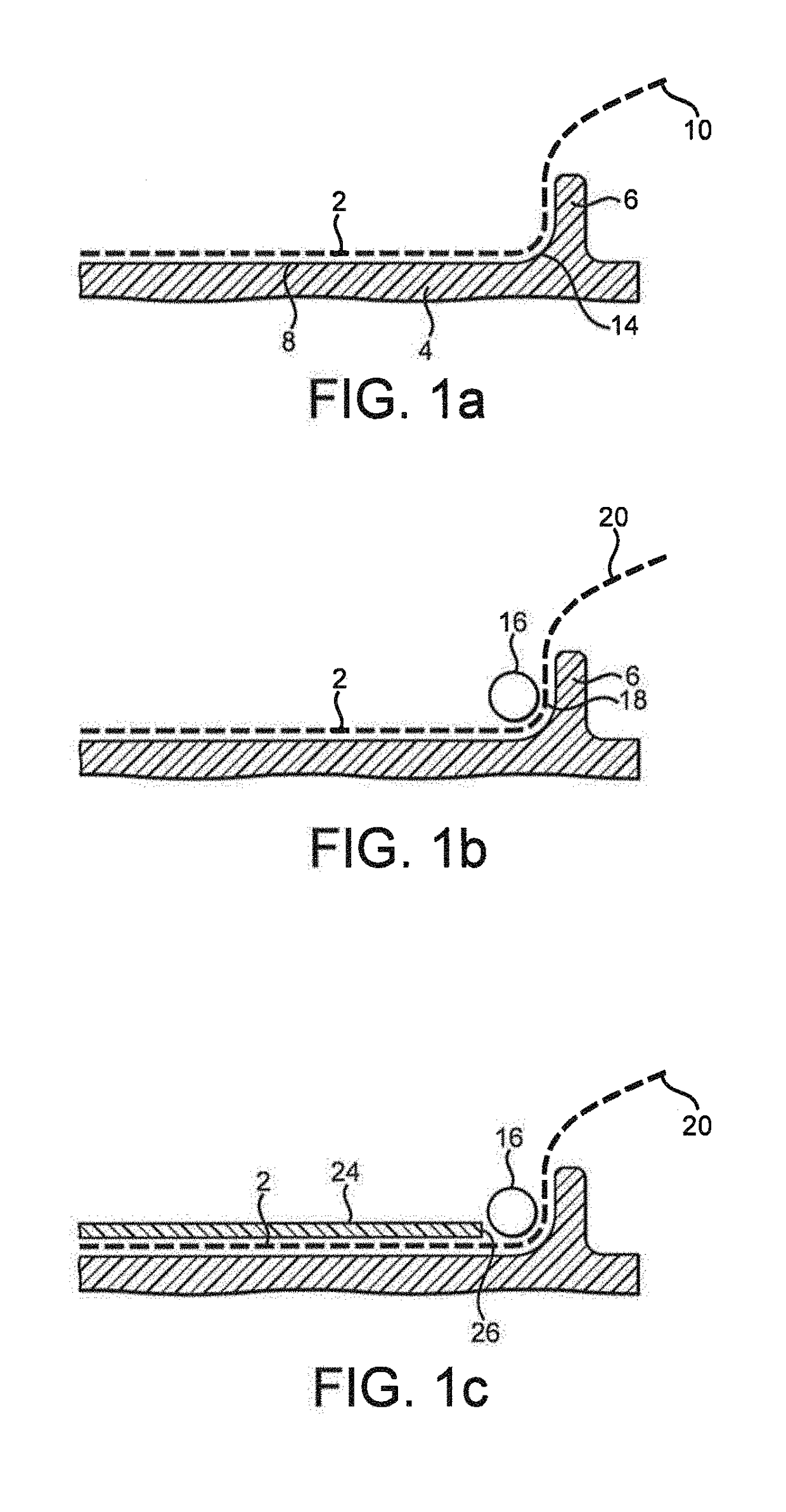
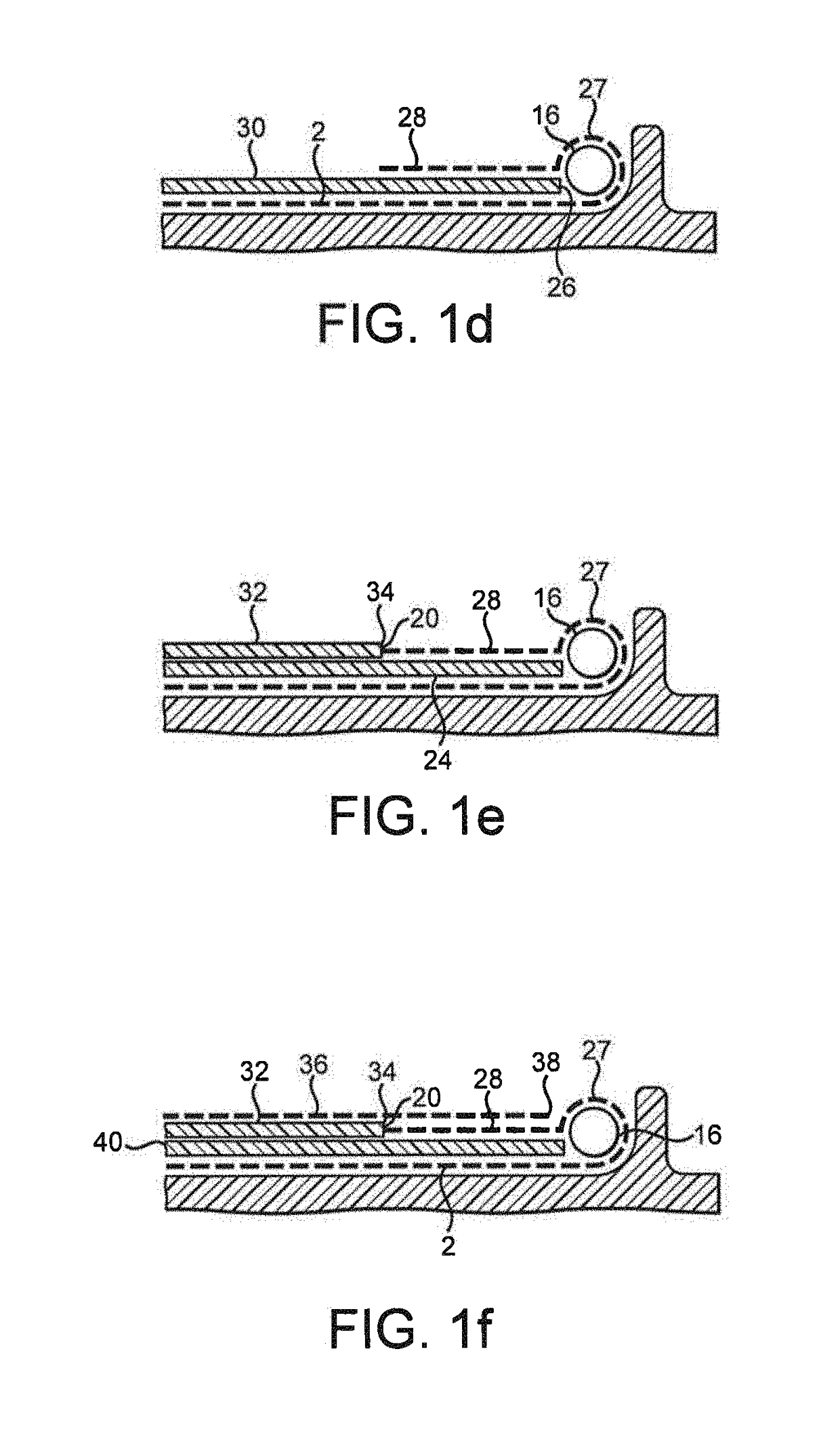
[0057]A cosmetic woven carbon component 1.2 m wide×1.1 m long with a nominal wall thickness of 1.27 mm was made by press moulding in a fixed cavity tool set Gurit SE160 and Gurit ST160 prepregs and a rope formed by winding three 24K dry carbon ends cut from a standard bobbin.

[0058]The first, second third and fourth plies, and the top, had the following properties as summarised in Table 1.

TABLE 1PlyProductProduct Description1PA13-SE160 / RC245T / 1250 / 245 gsm 3K Carbon 2 × 2621042% / POPATwill 0 / 90 woven 160 TgEpoxy prepreg with 42%resin content2SA23-ST160 / XC300C / 1270 / 300 gsm 12K Carbon Non643651% / S / SCrimp stitiched BiaxialPOPACarbon 160 Tg Epoxyprepreg with 42% resincontent2aThree 24K Carbon ends cut from a bobbin wereRopewound to form a rope by twisting the yarn oppositeInsertto that of the strand to form a stable rope3SA23-ST160 / XC300C / 1270 / 300 gsm 12K Carbon Non643651% / S / SCrimp stitiched BiaxialPOPACarbon 160 Tg Epoxyprepreg with 42% resincontent4PA13-SE160 / RC245T / 1250 / 245 gsm 3K Carbo...

example 2

[0063]The same components, preform mould and cure process were used as in Example 1 except that the carbon rope was replaced by a 3 mm diameter Vectran rope available for dingy and yachting rigging. Vectran is an aromatic polyester fibre available in commerce from Kuraray Co., Ltd. The rope was heat set for 30 min at 150° C. before use in order to increase its thermal stability. On demould a high visual quality was obtained in the majority of the part with a very minor aesthetic surface defect, still meeting the quality requirement, evident from approximately 2 mm of rope shrinkage.


PUM

PropertyMeasurementUnit
shrinkageaaaaaaaaaa
temperatureaaaaaaaaaa
widthaaaaaaaaaa

Abstract

A laminated moulded part of fibre-reinforced resin matrix composite material, the moulded part comprising a first ply comprising fibres impregnated with a resin, an outer surface of the first ply defining an outer surface of the laminated moulded part, a rope located around at least a part of a periphery of the first ply, the rope comprising a plurality of strands of fibres twisted together and impregnated with a resin, a second ply comprising fibres impregnated with a resin, the second ply at least partly covering an inner surface of the first ply, at least a portion of a peripheral edge of the second ply being located inwardly of a corresponding portion of the rope, and at least a portion of the periphery of the first ply being folded over so as to wrap around the rope and cover the corresponding peripheral edge of the second ply.

Description

FIELD OF THE INVENTION[0001]The present invention relates to a method of moulding a moulding material to form a laminated moulded part of fibre-reinforced resin matrix composite material, and to a laminated moulded part of fibre-reinforced resin matrix composite material. In particular, the present invention relates to such a method which is for manufacturing moulded parts composed of fibre reinforced resin matrix composite materials, such as, for example, panels, more particularly automotive body panels, having a high quality surface finish.BACKGROUND OF THE INVENTION[0002]It is known to produce moulded parts for various applications, and having various shapes and configurations, by moulding materials including polymer resins, in particular for the manufacture of moulded parts composed of fibre reinforced resin matrix composite materials. Such composite materials are typically manufactured from moulding materials which may typically comprise, for example, (a) the combination of dry...

Claims


Application Information

Patent Timeline
Patent Type & Authority Applications(United States)
IPC IPC(8): B29C70/70B29C70/46B32B5/02B32B27/38B29C70/22B29C53/38B29C53/36B29K63/00B29K105/08B29K307/04B29K707/04
CPCB29C70/70B32B5/024B32B27/38B29C70/467B29C53/387B29C2053/365B32B2262/106B29K2105/089B29K2307/04B29K2707/04B29K2063/00B29C70/222B29C70/34B29C70/302B29C70/06B32B3/04B32B2305/076C08J5/24
Inventor JONES, DANIEL THOMASMAIN, STEPHEN PATRICKWATTS, DANNY KEITH
Owner GURIT (UK) LTD
Why Eureka
Try Eureka