Lift, drop, swing, and attenuation apparatus and method

a technology of attenuation apparatus and method, which is applied in the field of new systems and methods for climbing walls, pendulum falls, swing mechanisms, etc., to achieve the effects of rapid attenuation, reduced labor costs, and reduced labor costs

Pending Publication Date: 2022-02-24
ZIPHLDG
View PDF54 Cites 3 Cited by
  • Summary
  • Abstract
  • Description
  • Claims
  • Application Information

AI Technical Summary

Benefits of technology

[0006]What is lacking is throughput at a safe condition with minimal labor cost and training. Also lacking is the fun of rock climbing, combined with a swing for a safe pendulum fall, rapid attenuation for throughput, and an option for additional drops before termination. It would be an advance in the art to provide a system that combines a climbing wall, engineered to this specific purpose, with a support system for a swing acting as a belay system. It would also be an advance to have a swing that loads faster, provides more variations of “trajectory,” and can be stilled more quickly to shorten the “decay time” or “runout time.”

Problems solved by technology

Also lacking is the fun of rock climbing, combined with a swing for a safe pendulum fall, rapid attenuation for throughput, and an option for additional drops before termination.
A climber falling, missing a hold, finishing a route, or timing out may result in the belay system lifting the climber to the top.

Method used


Image

  • Lift, drop, swing, and attenuation apparatus and method
  • Lift, drop, swing, and attenuation apparatus and method
  • Lift, drop, swing, and attenuation apparatus and method

Examples


example

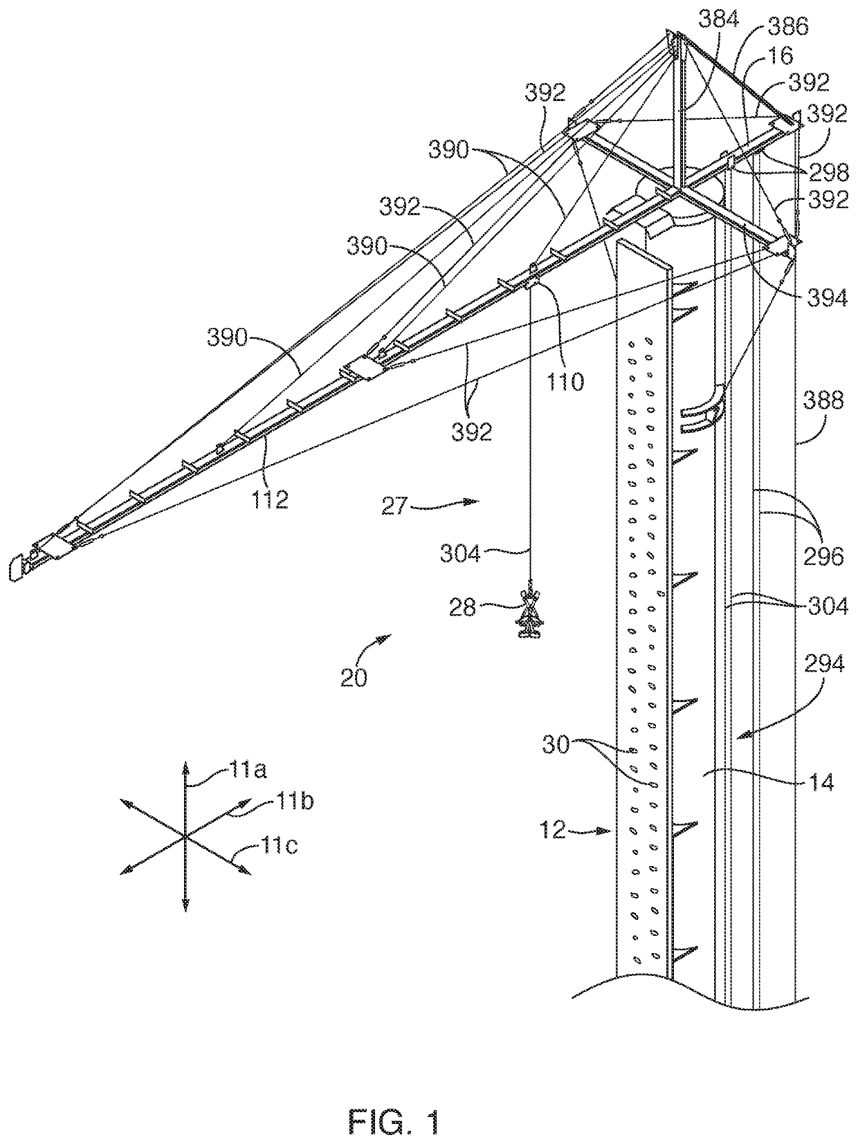
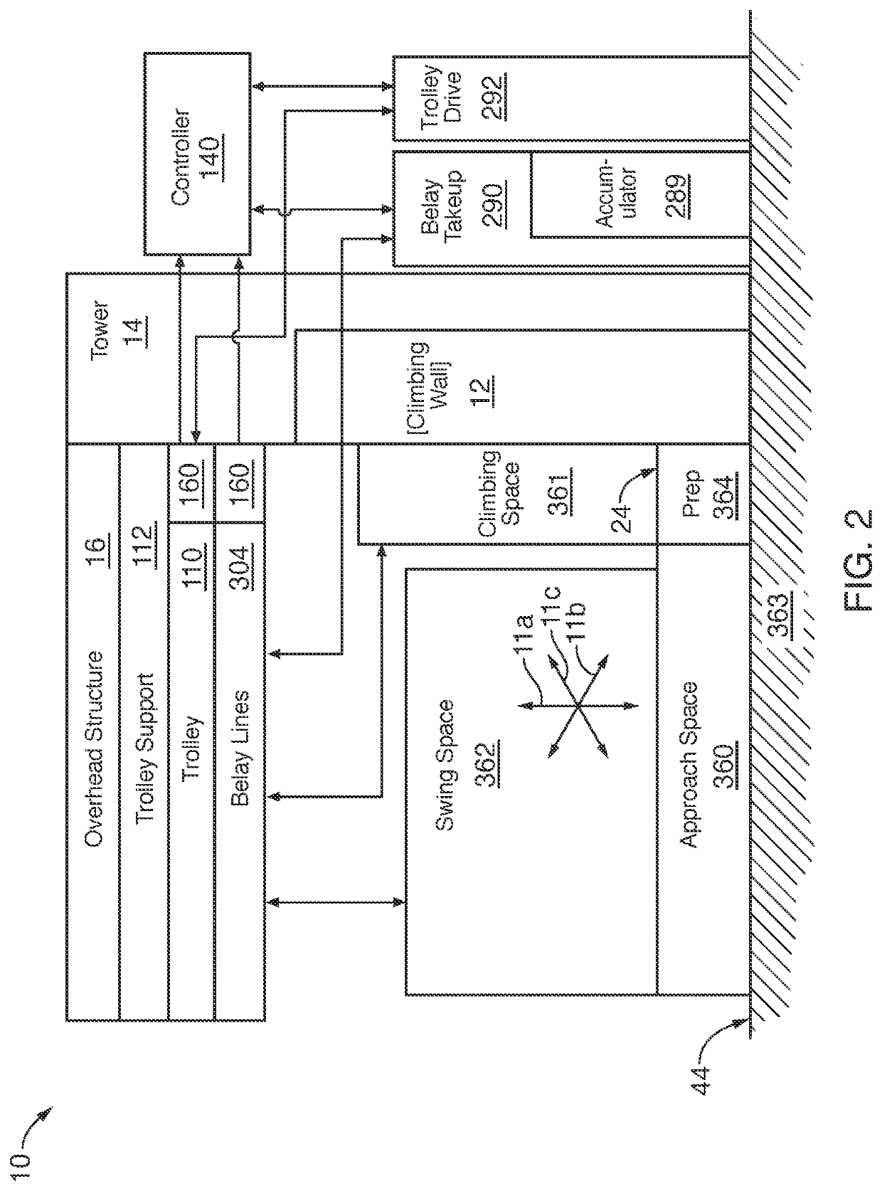
[0229]Here's how a system 10 works in one current embodiment in accordance with the invention. Once the cycle is initiated, harnessed patrons have 20 seconds to climb as high up the wall 12 as they can before time runs out, at which point the ZipWhipper™ 10 takes over and pulls them to the top of the wall. The height climbed and time of each climber is recorded by the controller 140, allowing participants 60 to compete against each other.

[0230]At the top of the climbing wall 12, participants 60 are given a short time (a second to a few seconds) to look around, place feet in a rappelling stance, and contemplate their height before the ZipWhipper™ drops them backwards into a breathtaking pendulum free fall trajectory 410, swinging them outward 11b away from the wall 12. This part simulates a “lead fall” when rock climbing.

[0231]What happens next is a function of the attraction's unique technology. The ZipWhipper's swing dampening system measures each climber's swing time, and automati...


PUM


Abstract

A tower may support a horizontal track and a vertical climbing wall therebelow. A trolley, movable along the track, may be selectively driven toward and away from the tower by belay lines, line and capstan, positive drive, or some combination. Belay lines reeved over pulleys on the trolley may be taken up and paid out independently from the trolley, while fixed or moving. A rider may climb, be lifted, or both to near the intersection of the tower and track, from there to fall or jump into a controllable trajectory such as swinging or simulating a parachute landing. Swinging may be rapidly attenuated almost entirely by “bumps,” lifting a rider to remove momentum and kinetic energy as a rider moves toward a pivot point overhead. Control may be simplified based on sensing and using timing past bottom dead center (BDC).

Description

RELATED APPLICATIONS[0001]This application claims the benefit of U.S. provisional Patent Application Ser. No. 63 / 089,657, filed Oct. 9, 2020 and U.S. provisional Patent Application Ser. No. 63 / 073,288, filed Sep. 1, 2020. This application is a continuation in part of U.S. patent application Ser. No. 17 / 217,660, filed Mar. 30, 2021, which is a continuation (divisional) application of U.S. patent application Ser. No. 16 / 431,524, filed Jun. 4, 2019, now issued as U.S. Pat. No. 10,960,252 on Mar. 30, 2021; which claims the benefit of U.S. provisional Patent Application Ser. No. 62 / 680,909, filed Jun. 5, 2018, U.S. Provisional Patent Application Ser. No. 62 / 757,577, filed Nov. 8, 2018, and U.S. Provisional Patent Application Ser. No. 62 / 839,665, filed Apr. 27, 2019. All of the foregoing are hereby incorporated herein by reference in their entireties.[0002]This patent application hereby incorporates herein by reference the following patents: U.S. Pat. No. 10,053,115, issued Aug. 21, 2018,...

Claims


Application Information

Patent Timeline
Patent Type & Authority Applications(United States)
IPC IPC(8): A63B9/00A63B69/00A63B21/00
CPCA63B9/00A63B21/4007A63B69/0048A62B1/06A63B2009/006A63B2244/08A63B2244/081B64D23/00A63G2031/002A63G31/00A63B2220/13A63B2220/16A63B2220/62A63B2220/801A63B2220/52A63B2220/51A63B2220/56A63B71/023A63B2071/0072A63B2071/0081A63B2071/0063A63B24/0003A63B24/0021A63G9/12A63G9/14
Inventor CYLVICK, ERIC
Owner ZIPHLDG
Why Eureka
Try Eureka