Fluid filter with localized flow attachment

a technology of flue gas filter and localized flow, which is applied in the direction of moving filter element filter, filtration separation, separation process, etc., can solve the problem of pre-filling being detrimental

Active Publication Date: 2009-01-15
CUMMINS FILTRATION IP INC
View PDF10 Cites 62 Cited by
  • Summary
  • Abstract
  • Description
  • Claims
  • Application Information

AI Technical Summary

Benefits of technology

[0004]The following technical disclosure describes an improved fluid filter. The fluid filter described herein includes a housing having a filter media disposed therein. A flow attachment member is configured to communicate fluid to be filtered to the filter media, and is configured to communicate fluid filtered by the filter media out of the fluid filter. The flow attachment member includes a structure that is configured to localize fluid flow both into and out of the fluid filter. The flow attachment member further includes a seal structure to substantially prevent or at least confine leakage.
[0005]Some benefits of such a fluid filter can include allowing for a more clean service, since flow into and out of the fluid filter is localized within the flow attachment member. As a result, a filter can be provided that is more environment friendly and is more pleasing to customers and users. The fluid filter described herein also can substantially prevent or at least confine leakage to a localized area and away from proximity of edges of the housing, since a seal structure is provided on the flow attachment member. Thus, additional external and internal seals can be eliminated, where a fluid filter can be provided that is relatively inexpensive, reliable, and has fewer parts. Further, the flow attachment can eliminate the need for a nutplate as employed in many fluid filters, such as in spin-on type fluid filters. The flow attachment can provide a unique head and filter interface that may give OEM improved aftermarket business.
[0006]Even further, the flow attachment member can provide a benefit of pre-filling a fluid filter in the unfiltered containment region, such as the “dirty side.” For example, traditional fuel filters are pre-filled before installation in the clean compartment region (or “clean side”). In such flow configurations, the pre-filled fluid is already on the clean side and is allowed to enter the fuel system at first. Such pre-filling can be detrimental to newer high-pressure common rail fuel systems that require fine particle filtration. The flow attachment member disclosed herein can utilize a flow redirection concept through the flow attachment member that effectively diverts pre-filled fluid through the filtration media before it can enter the fuel system. That is, the flow attachment member described herein allows for a pre-filtering function of the pre-filled fluid before the fluid is allowed to enter exit the fluid filter.

Problems solved by technology

Such pre-filling can be detrimental to newer high-pressure common rail fuel systems that require fine particle filtration.

Method used


Image

  • Fluid filter with localized flow attachment
  • Fluid filter with localized flow attachment
  • Fluid filter with localized flow attachment

Examples


Embodiment Construction

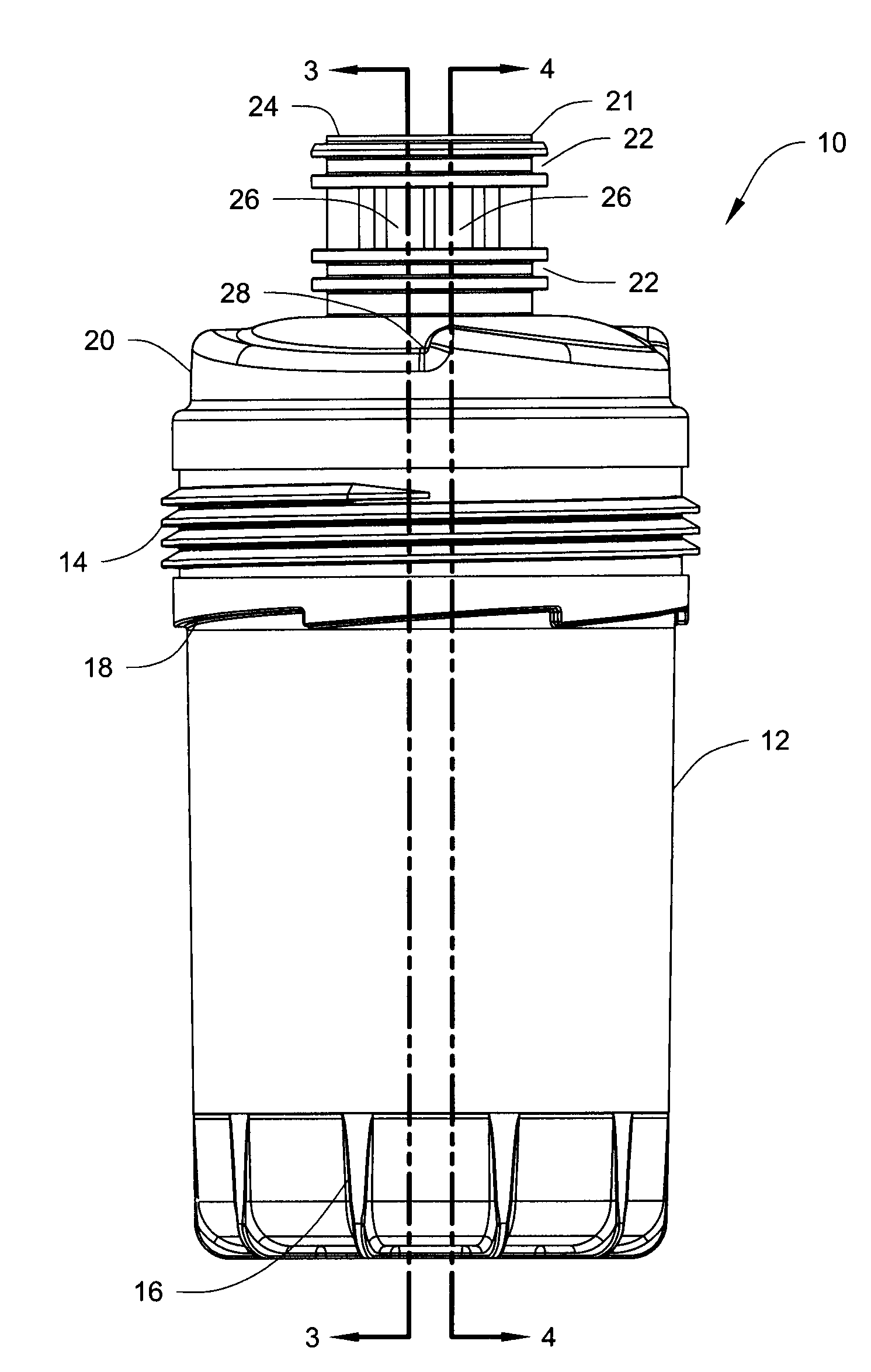
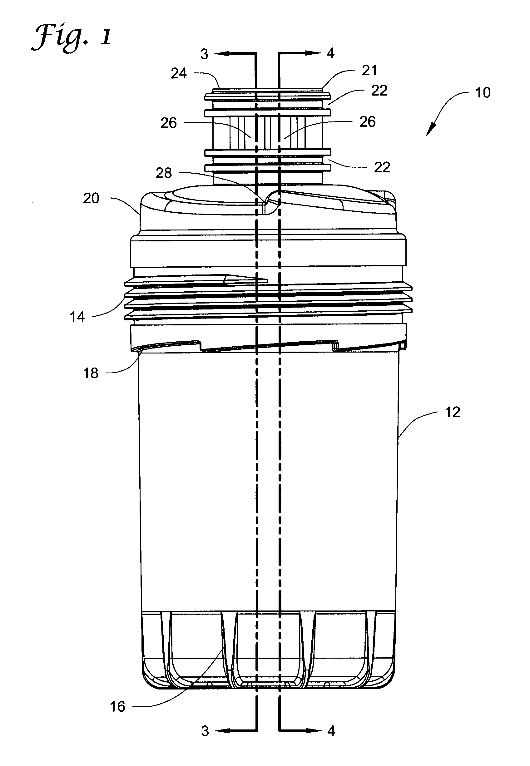
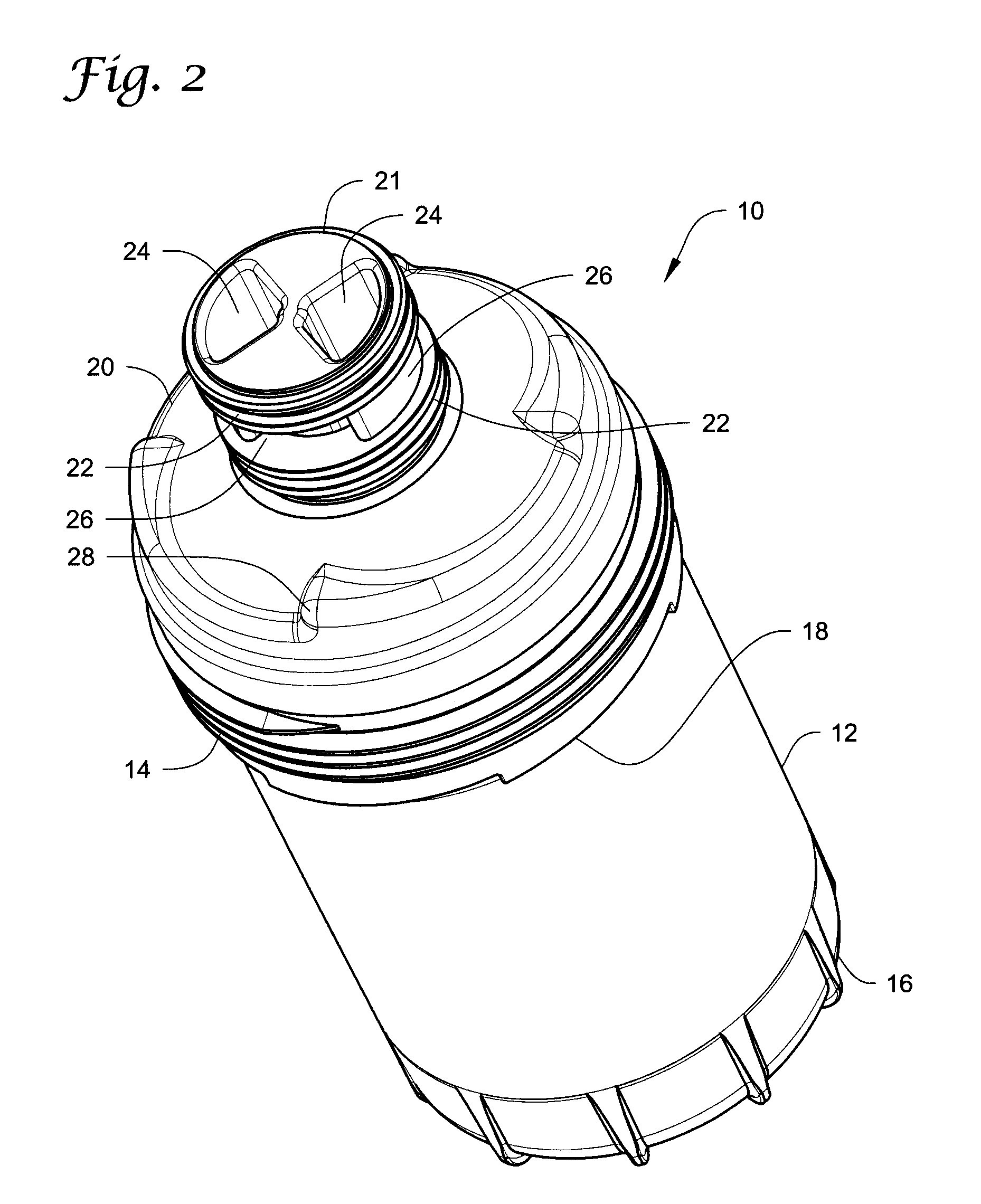
[0043]The fluid filter described herein generally provides a flow structure that is localized and sealed. For example, the fluid filter described herein includes a flow attachment member configured to communicate fluid to be filtered by a filter media into the fluid filter, and configured to communicate fluid filtered by the filter media out of the fluid filter. The flow attachment member is configured to localize fluid flow both into and out of the fluid filter within a flow structure of the flow attachment member. The flow attachment member further includes a seal structure disposed on an outer surface of the structure of the flow attachment member. The fluid filter described herein can allow for cleaner servicing of the fluid filter, and can allow for a pre-filtering function, since flow into and out of the fluid filter is localized within particular flow paths created by the flow attachment member. The fluid filter described also can substantially prevent or at least confine lea...


PUM

PropertyMeasurementUnit
areaaaaaaaaaaa
resilientaaaaaaaaaa
pressureaaaaaaaaaa

Abstract

A fluid filter device is described, where a flow attachment member provides a unique interface between the filtering element and a filter head. The fluid filter described herein generally provides a flow structure that is localized and sealed. The flow attachment member is configured to communicate fluid into and out of the fluid filter, and is configured to localize fluid flow both into and out of the fluid filter within a separating structure of the flow attachment member. The flow attachment member further includes a seal structure configured to substantially prevent or at least confine leakage to a localized area away from proximity of the edges of the housing.

Description

FIELD[0001]A fluid filter is disclosed having a flow attachment that localizes fluid flow into and out of the fluid filter within a separating structure of the flow attachment, and where the separating structure includes a sealing structure disposed thereon.BACKGROUND[0002]Fluid filters are widely known and used in a variety of systems requiring filtration of a working fluid. After use and wear, many fluid filters eventually must have their filter elements serviced and / or replaced, and many fluid filters themselves must be removed in order to be serviced and / or replaced. Thus, ease and cleanliness of service have been concerns in fluid filter design. Preventing leakage or at least confining leakage has presented challenges in the sealing structure of such fluid filters. In one example shown in FIG. 25, a typical spin-on filter 900 includes a metallic nutplate 914 that typically is employed for allowing unfiltered fluid to flow into opening 922. The unfiltered fluid filters through a...

Claims


Application Information

Patent Timeline
Patent Type & Authority Applications(United States)
IPC IPC(8): B01D35/30B01D46/00
CPCB01D29/114B01D2201/302B01D2201/34B01D29/117B01D29/58B01D29/902B01D35/30
Inventor SOUTH, KEVIN C.BAGCI, ISMAIL
Owner CUMMINS FILTRATION IP INC
Why Eureka
Try Eureka