
Narrow ceramic self-ligating orthodontic bracket

Inactive Publication Date: 2009-01-15
3M INNOVATIVE PROPERTIES CO
View PDF23 Cites 23 Cited by
  • Summary
  • Abstract
  • Description
  • Claims
  • Application Information

AI Technical Summary

Benefits of technology

[0011]The present invention is directed to a ceramic orthodontic bracket that offers a significant advantage over previously known self-ligating brackets. In one aspect of the invention, the bracket includes a generally “C”-shaped latch for releasably retaining an archwire in the archwire slot. This “C”-shaped latch is located between the mesial and distal sections of the bracket. The central location of the clip is advantageous because it enables the bracket to have a reduced mesial-distal width compared to brackets that use mesial and distal clips. A reduced mesial-distal width, in turn, alleviates potential problems with interference between adjacent brackets during bonding. As an additional advantage, reducing mesial-distal width increases the inter-bracket distance. With greater distance for the archwire to deflect or “flex” between brackets, the clinician is able to install larger archwires into the patient sooner in treatment, again enhancing efficiency. By providing tiewings in addition to the centrally-located latch, this bracket gives the clinician flexibility of using the latch for ligation early in treatment, and then increasing sliding resistance by using an elastic O-ring for ligation later in treatment if desired.
[0013]Optionally, the spacing between the mesial and distal sections of the bracket may exceed the mesial-distal width of the clip by a certain amount to further assist in debonding. Other optional features include an archwire slot liner, or tabs disposed at the ends of the clip to facilitate connection of the latch to the bridge section.

Problems solved by technology

This latch configuration, however, poses challenges for ceramic self-ligating brackets, which tend to be slightly larger than their metal counterparts.
Specifically, problems may arise when bonding brackets to small teeth such as lower anteriors.
Because lower anterior teeth are small, collisions (or interferences) can occur between adjacent brackets during bonding and prevent brackets from being located optimally on the tooth.
Even in cases where the teeth are sufficiently large, bracket interferences may still occur if teeth are overlapping or have facial (i.e. towards the patient's cheek or lips) surfaces that are angled toward each other.
Because lower anterior teeth are often crooked and induce these interferences, the clinician is frequently unable to successfully bond all the brackets on the first appointment and postpones bonding one or two brackets until such time that sufficient space has been created.
This in turn extends treatment time and reduces the efficiency of treatment.
However, this too is disadvantageous because these same brackets will often need to be debonded and re-positioned later in treatment.
Bracket re-positioning is not ideal because it requires an additional time investment by the clinician and another potentially uncomfortable procedure for the patient.

Method used


Image

  • Narrow ceramic self-ligating orthodontic bracket
  • Narrow ceramic self-ligating orthodontic bracket
  • Narrow ceramic self-ligating orthodontic bracket

Examples


Embodiment Construction

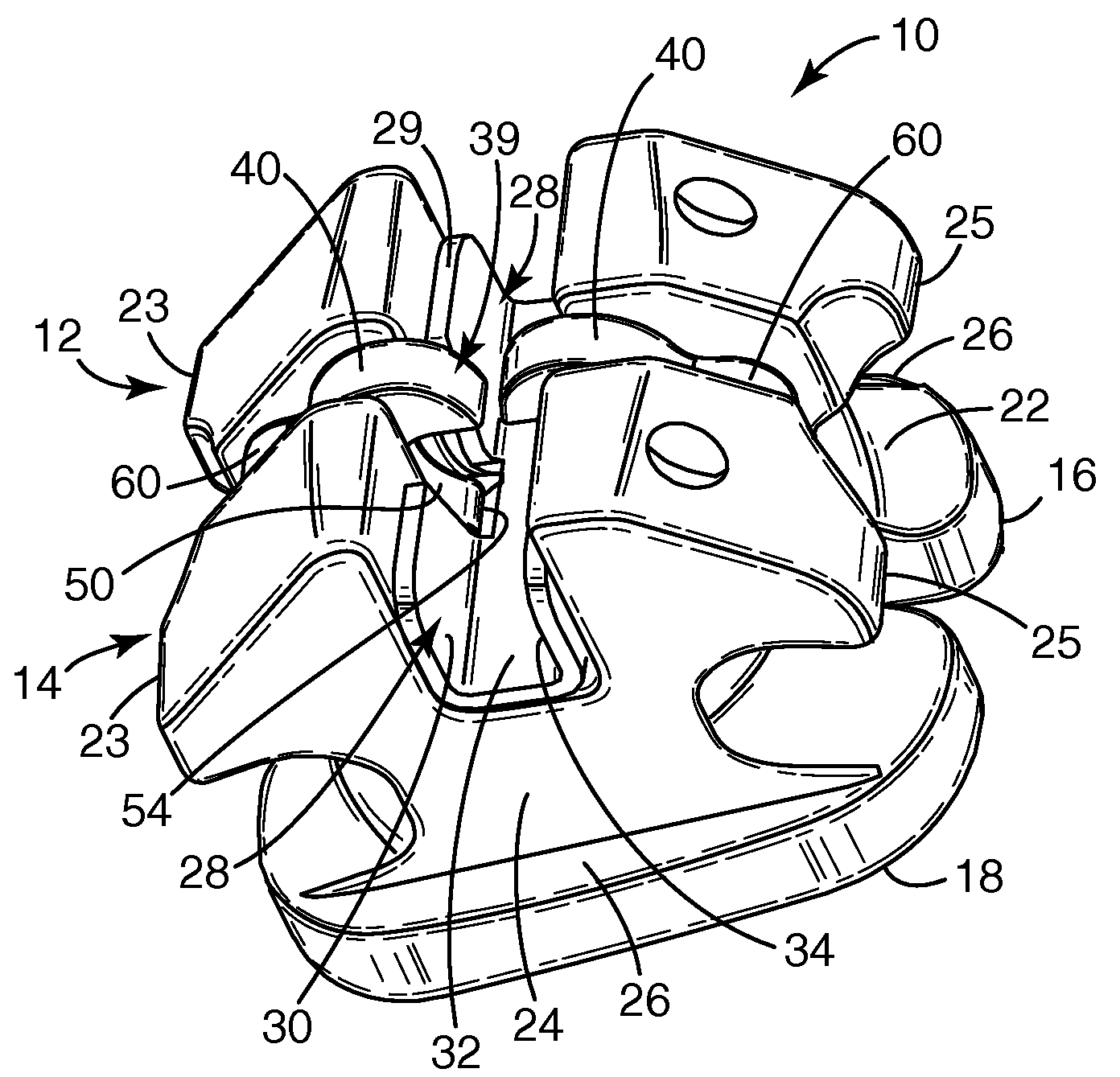
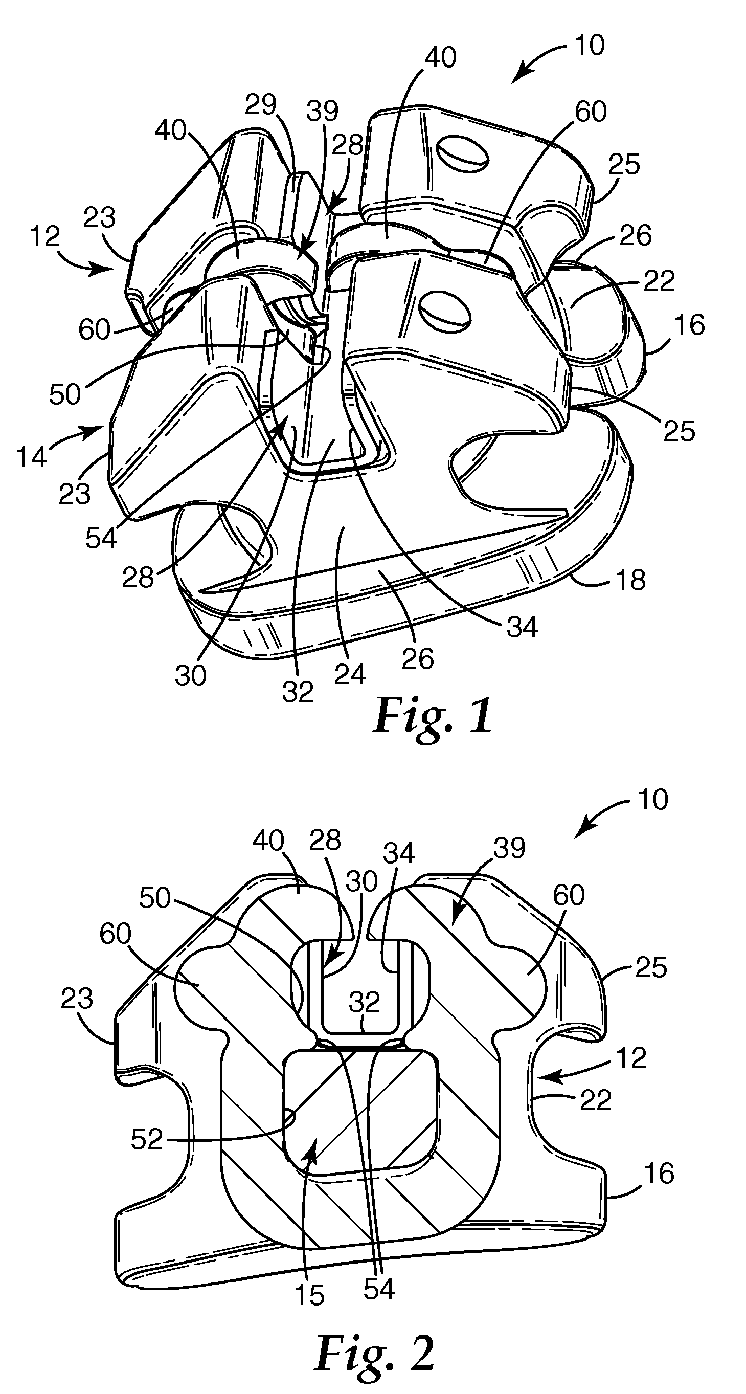
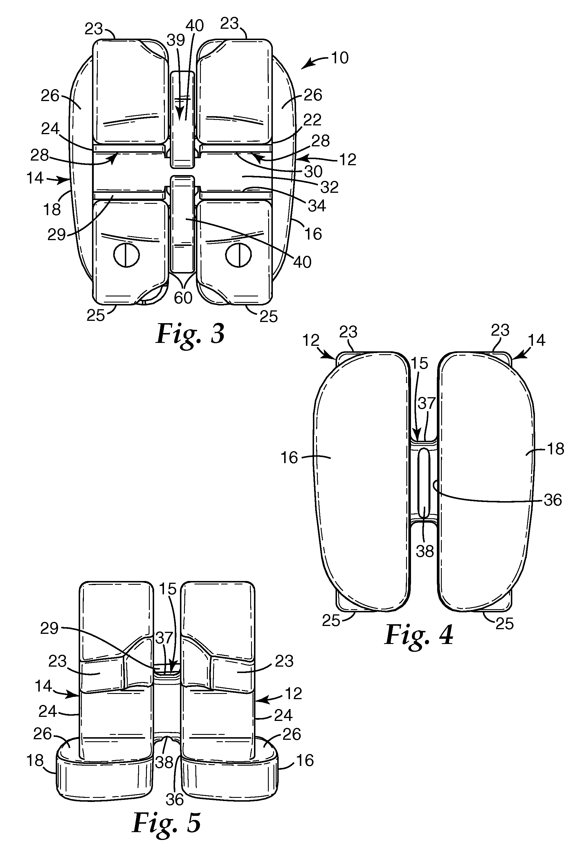
[0029]An exemplary bracket in accordance with one embodiment of the invention is shown in FIGS. 1-3, and broadly designated by the numeral 10. This particular bracket is adapted to be bonded to the facial surface of a lower anterior tooth of a patient. Alternative embodiments may include brackets designed for bonding to other teeth in the mouth such as cuspids or bicuspids, and molars. Embodiments including buccal tubes or any other type of appliance capable of receiving an archwire for controlling movement of teeth during orthodontic treatment are possible as well.

[0030]The bracket 10 includes mesial section 12 and distal section 14, connected to each other by bridge section 15 (visible in the cross-sectional view of FIG. 2). Mesial section 12 and distal section 14 include mesial base 16 and distal base 18, respectively, that are adapted for bonding bracket 10 directly to the tooth of a patient by means of a suitable adhesive. Preferably the bottom surfaces of mesial base 16 and di...


PUM


Abstract

A ceramic orthodontic bracket has a centrally located clip for retaining an archwire in an archwire slot. The body of the bracket includes a mesial section, a distal section, and a bridge section, wherein the bridge section extends through, and retains, the clip. The bridge section also includes a recess adjacent to the bridge section that facilitates debonding of the bracket from a patient's tooth. Preferably there are gaps on one or both sides of the clip to allow space for debonding of the bracket by applying a mesial-distal compressive force on the bracket and fracturing the bracket along the recess. This configuration allows the overall mesial-distal width of the bracket to be reduced, thereby facilitating the bonding of brackets to narrow and / or maloccluded teeth. Another embodiment includes a stop member that is connected to the base of the bracket and retains the clip on the bridge section.

Description

BACKGROUND OF THE INVENTION [0001]1. Field of the Invention[0002]The present invention broadly pertains to an appliance used in orthodontic treatment. More particularly, this invention pertains to a ceramic orthodontic appliance that includes a clip for releasably retaining an archwire in an archwire slot of the appliance.[0003]2. Description of the Related Art[0004]Orthodontic therapy is a specialized type of treatment within the field of dentistry associated with the supervision, guidance and correction of malpositioned teeth into proper locations. Orthodontic treatment can be useful in correcting defects in a patient's bite (also called occlusion) along with promoting better hygiene and improving the overall aesthetics of the teeth.[0005]Orthodontic treatment often involves the use of tiny slotted appliances known as brackets, which are generally affixed to the patient's anterior, cuspid, and bicuspid teeth. After the brackets have been placed on the teeth, an archwire is receive...

Claims


Application Information

Patent Timeline
IPC IPC(8): A61C7/16
CPCA61C7/28A61C2201/007A61C7/30
Inventor POSPISIL, JIRINA V.THORSTENSON, GLENYS A.HO, JOYCE C.BRENNAN, JOAN V.
Owner 3M INNOVATIVE PROPERTIES CO
Learn More