Method for fastening an implant to bone tissue and corresponding implant system

a technology of bone tissue and implants, applied in the field of medical engineering, can solve the problems of reducing the lifespan of bearing elements, additional space, and inability to apply universally, and achieve the effect of limited accuracy

Active Publication Date: 2009-01-15
WOODWELDING
View PDF30 Cites 68 Cited by
  • Summary
  • Abstract
  • Description
  • Claims
  • Application Information

AI Technical Summary

Benefits of technology

[0012]In most embodiments of the method according to the invention, the step of anchoring the fasteners and the step of connecting the implant with the anchored fasteners are essentially independent of each other and are executed after each other. Therefore, different embodiments of these two steps as well as different embodiments of proximal and distal sides of the fasten

Problems solved by technology

Screws extending through the implant require through bores and these bores and, subsequently, the heads of the screws inserted therein constitute friction points on the joint side of the implant, which is particularly detrimental if the implant constitutes the articulating surface (without bearing element) and the bores therefore are part of the articulating surface.
Such friction points may also reduce the lifespan of a bearing element if it is movable on

Method used


Image

  • Method for fastening an implant to bone tissue and corresponding implant system
  • Method for fastening an implant to bone tissue and corresponding implant system
  • Method for fastening an implant to bone tissue and corresponding implant system

Examples


Embodiment Construction

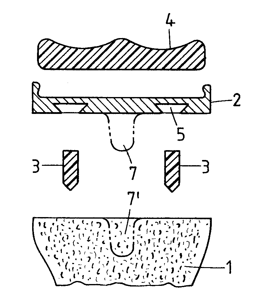
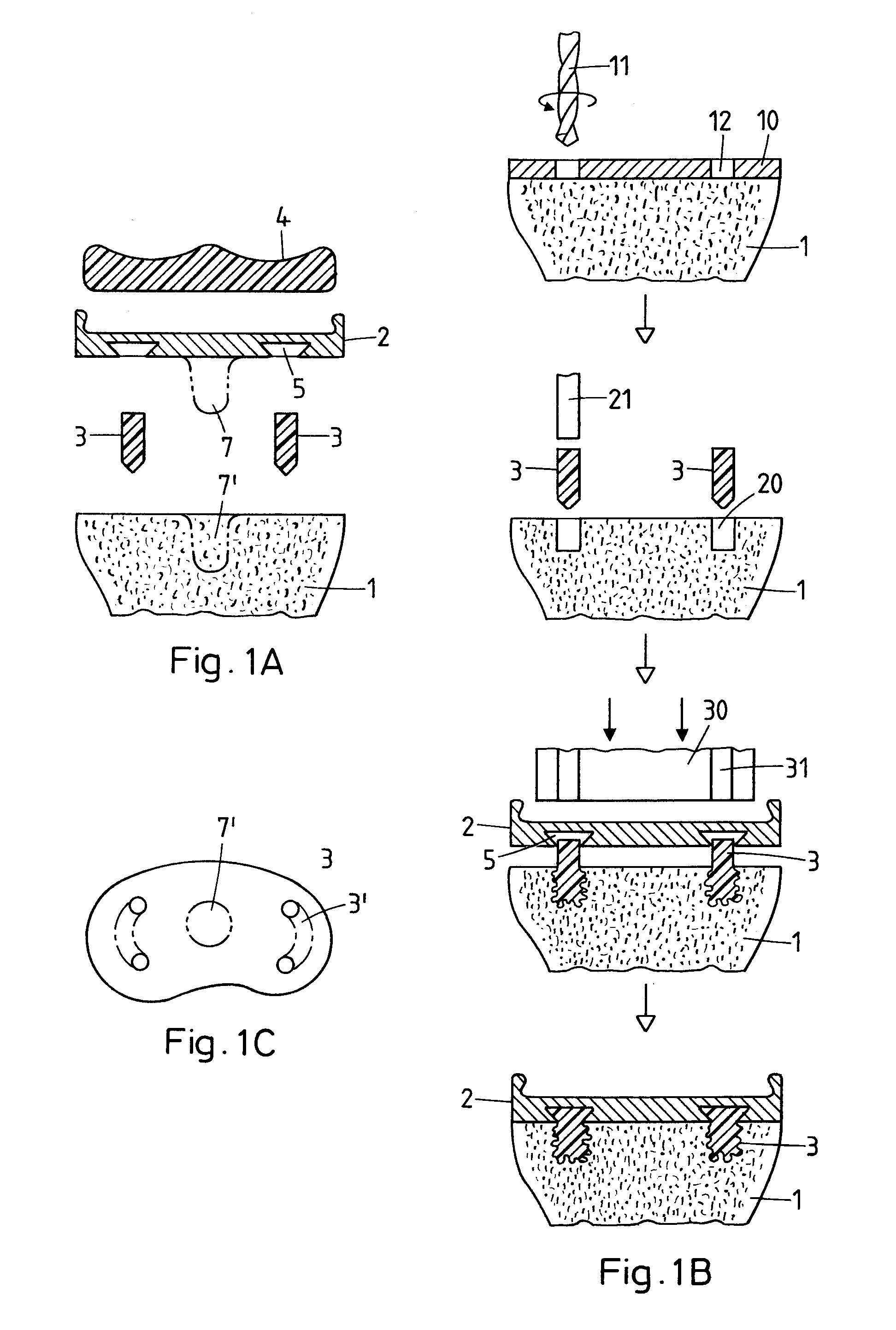
[0025]FIGS. 1A, 1B and 1C illustrate a first exemplary embodiment of the implant system and of the method for fastening the implant according to the invention. These Figs. illustrate the resurfacing of a tibia plateau (articulating surface) as an exemplary application. As already mentioned above, implant and method according to the invention are not only suitable for the resurfacing of a tibia plateau but essentially for any replacement of an articulating surface of a human or animal joint, wherein each specific application requires a corresponding adaptation of the implant regarding, in particular, shape and design of the joint side and a corresponding adaptation of the fasteners regarding number, dimensions and positions in relation to the bone and the implant. The named adaptations can be carried out by one skilled in the art without any problem. Implant and method as illustrated in FIGS. 1A to 1C are also suitable for supporting or stabilizing bones (e.g. after a fracture), wher...


PUM


Abstract

An implant designed e.g. as a replacement for an articulating surface of a human or animal joint is secured to the bone tissue with the aid of a plurality of fasteners (3). The implant (2) comprises a bone side to be brought into contact with the bone tissue, which bone side is equipped with a plurality of fastening structures restricted to this bone side. The fasteners (3) comprise a distal and a proximal side, wherein the distal side is equipped for being anchored in bone tissue and the proximal side is equipped for being connected with one of the fastening structures of the implant (2). The distal sides of the fasteners (3) are anchored in the bone tissue of the appropriately prepared bone and the implant (2) is then attached to the anchored fasteners (3) by connecting the fastening structures with the proximal sides of the fasteners (3), wherein the implant (2) is pressed against the proximal sides of the anchored fasteners (3).

Description

BACKGROUND OF THE INVENTION[0001]The invention lies in the field of medical engineering and concerns a method for fastening an implant to human or animal bone tissue as well as a corresponding implant system, wherein the implant may be designed e.g. as a replacement for the articulating surface of a joint, as a replacement for a larger bone section or another tissue or as an element for stabilizing a bone e.g. damaged by fracture. The invention further concerns a kit for carrying out the method.[0002]Replacements of articulating surfaces of human joints are known, in particular, in connection with the tibia plateau in the knee joint (articulating surface with concave and convex portions), the glenoid cavity on the shoulder-blade and the acetabulum on the pelvis (concave articulating surfaces), but are also used for articulating surfaces of other joints (elbows, wrists, ankles or digital joints), in particular also convex articulating surfaces such as e.g. the articulating surface of...

Claims


Application Information

Patent Timeline
IPC IPC(8): A61B17/08A61B19/00A61B17/04
CPCA61B17/68A61F2/30A61F2/30749A61F2/30767A61F2/3804A61F2/389A61F2/4081A61F2/42A61F2002/30065A61F2002/30332A61F2002/30382A61F2002/30457A61F2002/30604A61F2002/30616A61F2002/30772A61F2002/30777A61F2002/3082A61F2002/30845A61F2002/30878A61F2002/30892A61F2002/3412A61F2210/0071A61F2220/0033A61F2220/0058A61F2/30721A61F2002/30451A61F2002/30331
Inventor MAYER, JORGMULLER, ANDREA
Owner WOODWELDING
Why Eureka
Try Eureka