Tool holder for adapting a tool for its measurement and measuring arrangement and method for its calibration

a technology of tool holder and calibration method, which is applied in the direction of measuring/indication equipment, metal-working equipment, instruments, etc., can solve the problems of only being able to correct errors to a limited extent, affecting the measurement of calibration features negatively, and uncertainties in the optical identification of calibration features. , to achieve the effect of avoiding follow-up costs that arise from erroneous calibration, limited accuracy in the measurement of tools, and high degree of accuracy

Inactive Publication Date: 2011-04-14
NT TOOL CO LTD
View PDF10 Cites 1 Cited by
  • Summary
  • Abstract
  • Description
  • Claims
  • Application Information

AI Technical Summary

Benefits of technology

As a result of the specified method, a point of origin is available which is suitable as a reference point for measuring the tool. It is guaranteed by the method that this point of origin represents the zero-point of the tool to a high degree of accuracy, which is suitable as a reference point for the geometrical specification of the tool. The method allows an exchange of the tool holder without entailing limited accuracy in the measurement of a tool, which would generally be expected.
It is a specific advantage of the specified method for calibration of a measuring arrangement according to the invention that the optical axis of the optical measuring device is directed towards the central point of the circularity, such that the circular arch form of the outside edge of the calibration feature can be recorded with a high degree of accuracy. Aberrations depending on the distance to the central point of the image are flattened through this.
In a preferred embodiment, the method furthermore includes steps for checking the plausibility of the predefined horizontal standard calibration measure and the predefined vertical standard calibration measure. This embodiment is especially suitable for the calibration of measuring arrangements in which the tool holder is formed by an adapter which is carried by a spindle. The spindle also has a calibration feature so that the zero-point of the tool can also be established by means of this calibration feature. Initially, for the realization of this embodiment of the method according to the invention, the zero-point of the tool determinable in that way is to be established. For this purpose, for example, the method according to the invention can be carried out. Alternatively, a calibration feature according to the state of the art can be used. In many applications, the zero-point of the tool determinable in that way does not change, since the spindle is fixedly installed. Thus, it can be reverted to data stored for the zero-point of the tool. For checking the zero-point of the tool with regard to plausibility, the differences between the coordinates of the zero-point, established based on the calibration feature of the spindle, and the coordinates of the zero-point based on the calibration feature of the adapter are calculated. In case that one of the differences exceeds a predefined allowed tolerance range, a message is put out signalling an error. Alternatively or additionally, a message is put out if none of the differences exceeds the predefined allowed range, to signal that the adapter is fixed in the spindle correctly. An error can arise, for example, if there is swarf or dust between the adapter and the spindle when inserting the adapter into the spindle. Furthermore, an error can be caused when the predefined horizontal and vertical standard calibration measures were not recorded correctly. In this embodiment of the method, follow-up costs that arise from erroneous calibration are avoided.
A further preferred embodiment of the method furthermore includes steps for checking the correctness of the calibration of the measuring arrangement. In this embodiment of the method, one or multiple further geometrical characteristics of the calibration feature are chosen initially. The properties of these characteristics are known. The geometrical characteristics can, for example, be about a geometrical form whose properties are known. In a further step, the properties of the chosen characteristics of the calibration feature are meas-ured. The measured properties are compared to the known properties of these characteristics. A notification is given if the measured property of at least one of the characteristics differs from the known property of the appropriate characteristic at least in more than a predefined allowed range. This embodiment of the method allows, for example, to recognize dirt and deformation of the calibration feature and to avoid errors resulting from this. It is checked whether the recognized calibration feature complies with the expected calibration feature or whether the tool holder was confounded. The predefined allowed dimension can, for example, be adjustable by means of application software. It is a specific advantage of this embodiment of the method that follow-up costs that can arise by erroneous calibration or by usage of a wrong adapter are avoided. The user of the measuring arrangement is advised that there is an error.
A further embodiment of the method includes supplemental steps that are carried out during the measurement of a tool and assist in the measuring accuracy and thus are beneficial for the aim of the calibration. These steps include checking the rotation speed of an adapter forming the tool holder, particularly if the adapter is rotated by manual rotation of a spindle carrying the adapter. In this embodiment, the rotation speed is measured permanently, while the spindle is rotated. A message is put out if the measured rotation speed exceeds a predefined value for a maximum allowable rotation speed. The data measured, in case of incorrect rotation speed, are separated and can be recorded anew. In this embodiment of the method, data having a too great measurement uncertainty due to a too fast rotation of the tool are avoided. The user, who manually rotates the spindle, does not need to rotate the spindle unnecessarily slowly, so that the testing period is minimized without limiting the accuracy of the measurement.

Problems solved by technology

These optical errors can only be corrected to a limited extent and do therefore influence the measurement of the calibration feature negatively.
The remaining dirt leads to uncertainties in the optical identification of the calibration feature.
For establishing the calibration feature, the openings 04, 06 and the spheres 02, 03 have to be exactly arranged to each other, thus the establishment of the calibration feature is complex and the calibration feature is prone to damage.

Method used


Image

  • Tool holder for adapting a tool for its measurement and measuring arrangement and method for its calibration
  • Tool holder for adapting a tool for its measurement and measuring arrangement and method for its calibration
  • Tool holder for adapting a tool for its measurement and measuring arrangement and method for its calibration

Examples


Embodiment Construction

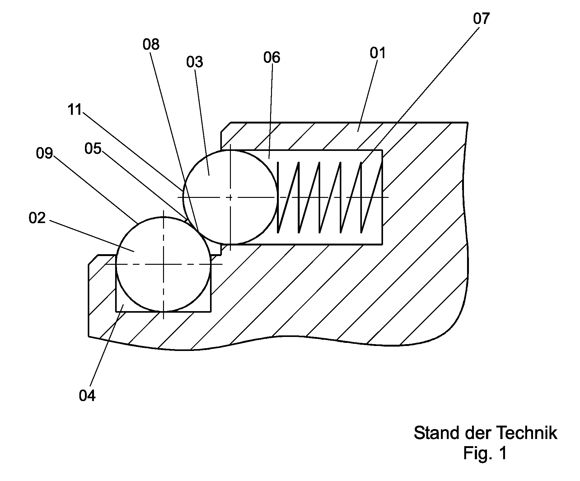
FIG. 1 shows a calibration feature with two spheres according to the state of the art, which is discussed above.

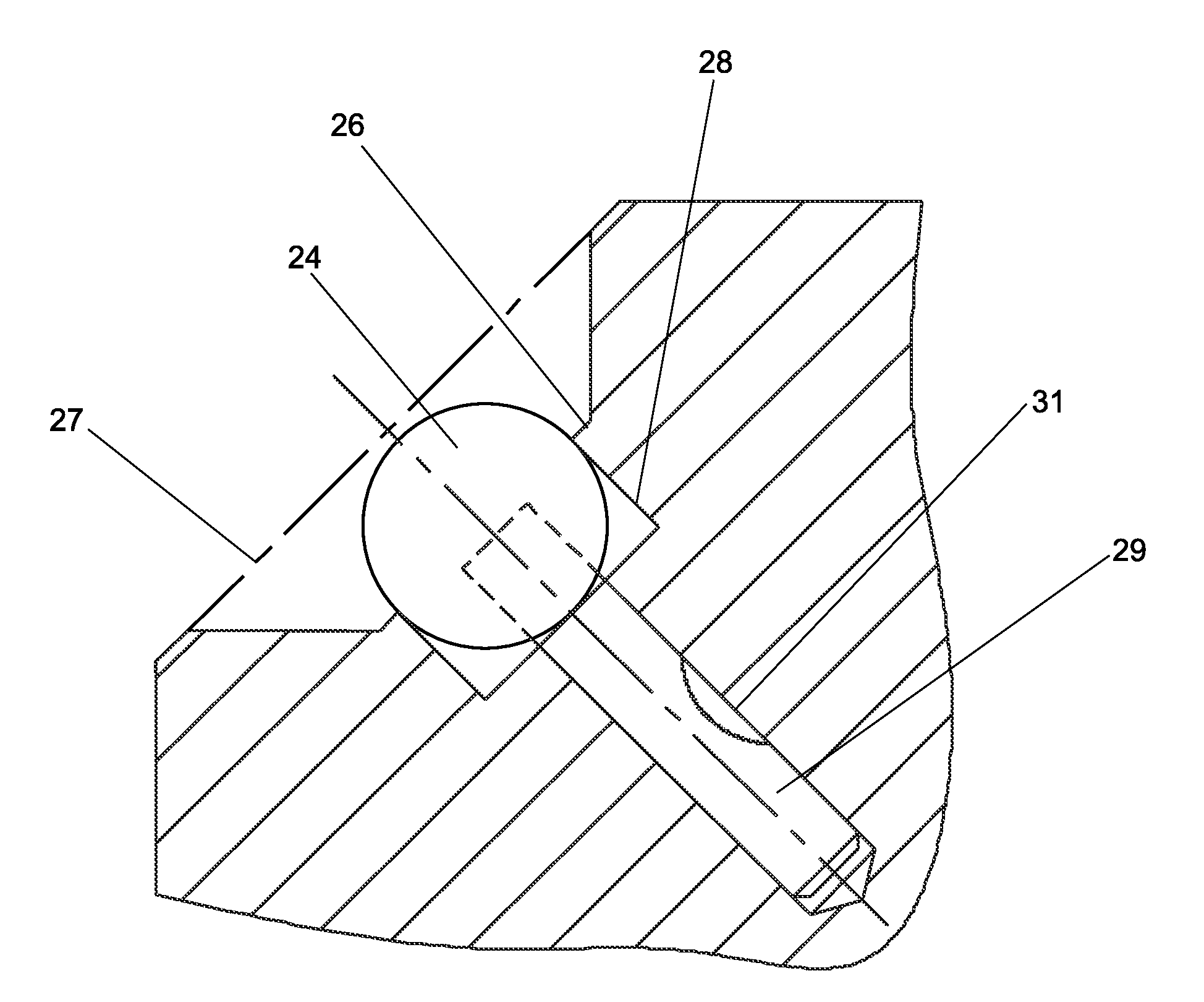
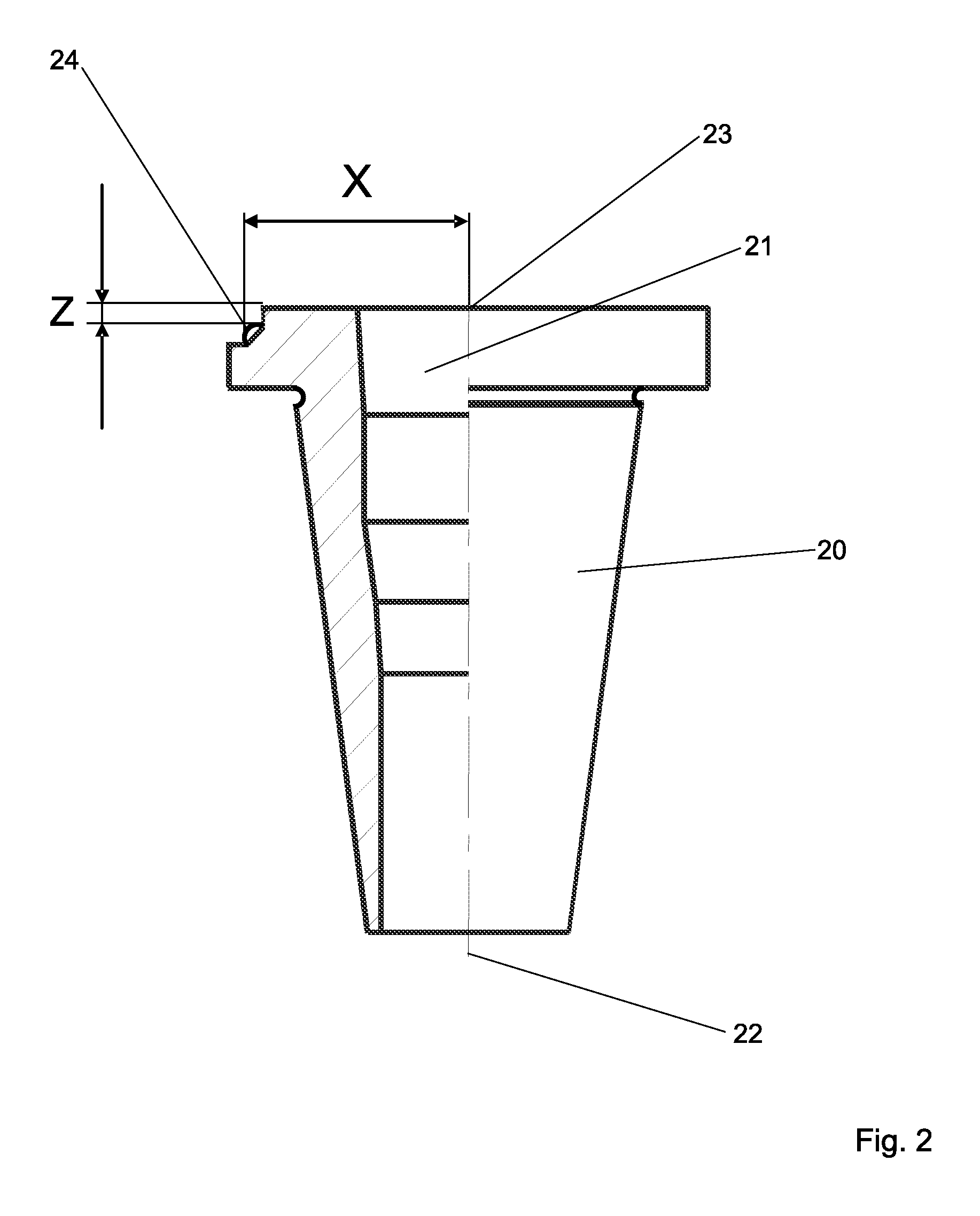
FIG. 2 shows a preferred embodiment of a tool holder according to the invention in the form of an adapter. The adapter is designated for being fixed in a rotatable spindle of a tool presetter (not shown) and to adapt a tool that is to be measured. Initially, the adapter includes a cylindrically symmetric base body 20 that is to be fixed in the spindle by its outer surface. The base body does not necessarily need to be cylindrically symmetric, but can, for example, be formed as a triangular shape of constant width.

The cylindrically-symmetric base body 20 has an inner cavity 21 which is also formed to be cylindrically symmetric and serves the adaption of the tool that is to be measured. A symmetry axis 22 of the cylindrically-symmetric base body 20 is design to form a rotational axis around which the adapter, the spindle and the tool to be measured will rotate in order to me...


PUM


Abstract

The present invention relates to a tool holder for adapting a tool to be measured in a measuring arrangement. Such tool holder can, for example, include a spindle or an adapter of a tool presetter to be inserted in such spindle. Furthermore, this invention refers to a measuring arrangement for measuring of tools as well as a method for calibration of such measuring arrangement to a zero-point of the tool.

Description

STATEMENT OF RELATED APPLICATIONSThis application claims priority of German Application No. 102009044206.5, filed Oct. 8, 2009, the contents of which are incorporated herein by reference in its entirety.BACKGROUNDDE 101 24 275 B4 refers to a method and a measuring arrangement for the measurement of tools. The measuring arrangement includes a base plate with an adapting arrangement for adapting a tool that is to be measured and a coordinate slide that is installed at the base plate. The coordinate slide holds the measuring system to be geared towards the tool. The measuring system includes camera systems with connected units for image processing. The solution provided particularly refers to measuring arrangements, where several adapters are used for the position-defined arrangement of the tools in the measuring system to be able to measure several, if applicable, different tools in the measuring arrangement. In each case, the adapters include a basic module and one or multiple insert...

Claims


Application Information

Patent Timeline
Patent Type & Authority Applications(United States)
IPC IPC(8): G01B1/00
CPCB23Q17/2457
Inventor ESAKA, SHUICHIKUBO, SHINJIFUKAGAWA, KATSUTOSHI
Owner NT TOOL CO LTD
Why Eureka
Try Eureka