Apparatus and method for microphone positioning based on a spatial power density
Active Publication Date: 2013-06-06
FRAUNHOFER GESELLSCHAFT ZUR FOERDERUNG DER ANGEWANDTEN FORSCHUNG EV
View PDF11 Cites 24 Cited by
Summary
Abstract
Description
Claims
Application Information
AI Technical Summary
This helps you quickly interpret patents by identifying the three key elements:
Problems solved by technology
Method used
Benefits of technology
Benefits of technology
The proposed concepts described in this patent offer the advantage of being adaptable to different room conditions with no prior knowledge of the number or position of talkers or physical sound sources. This makes the system self-reliant and able to adapt to any scenario using only sound analysis. Unlike conventional technology, the position of the virtual microphone is computed by doing a semi-blind scene analysis and then changing it accordingly for different target applications. This approach improves accuracy and flexibility.
In many applications, it is not possible or feasible to place a spatial microphone in the desired position, which, for example, may be a position close to the one or more sound sources.
This either limits the application, or an estimation may be made, limits the accuracy.
Method used
Image
Click on the blue label to locate the original text in one second.
Reading with bidirectional positioning of images and text.
Examples
first embodiment
[0097]According to a first concept of a first embodiment, the center of the sound scene is obtained by computing the center of gravity of the SPD Γ(x,y,z). The value of Γ(x,y,z) may be s interpreted as the existing mass at point (x,y,z) in space.
second embodiment
[0098]According to a second concept of a second embodiment, the position in space with a minimum time dispersion of the channel shall be found. This is achieved by considering the root mean squared (RMS) delay spread. At first, for each point in space p=(x0, y0), a power delay profile (PDP) Ap(τ) is computed based on the SPD Γ(x, y, z), for instance using
Ap(τ)=∫x∫yΓ(x,y)·δ(t-τ)yx
where τ=√{square root over ((x−x0)2+(y−y0)2)}{square root over ((x−x0)2+(y−y0)2)} / c
[0099]From Ap(τ), the RMS delay is then calculated using the following equation:
τRMS,p=∫0∞(τ-τ_s)2Ap(τ)τ∫0∞Ap(τ)τ,
where Ts represents the mean delay of Ap(τ). The position for which the mean delay TRMS,p is minimum will represent the center of the sound scene.
third embodiment
[0100]According to a third concept of a third embodiment, which may be employed as an alternative to sound scene center estimation, a “circle-integration” is proposed. For example, in the 2D case, the SPD Γ(x, y) is convolved with a circle C(r,o), according to the following formula:
g(x,y)=Γ(x,y)*C(r,o)(x,y),
wherein r is the radius of the circle, and wherein o defines the center of the circle. The radius r may either be constant or may vary depending on the power value in the point (x,y). For example, high power in the point (x,y) may correspond to a large radius, whereas low power may correspond to a small radius. Additional dependencies on the power may also be possible. One such example would be to convolve the circle with a bivariate Gaussian function before using it for constructing function g(x, y). According to such an embodiment, the covariance matrix of the bivariate Gaussian function becomes dependent on the power in the position (x,y), i.e., high power corresponds to low v...
PUM
Abstract
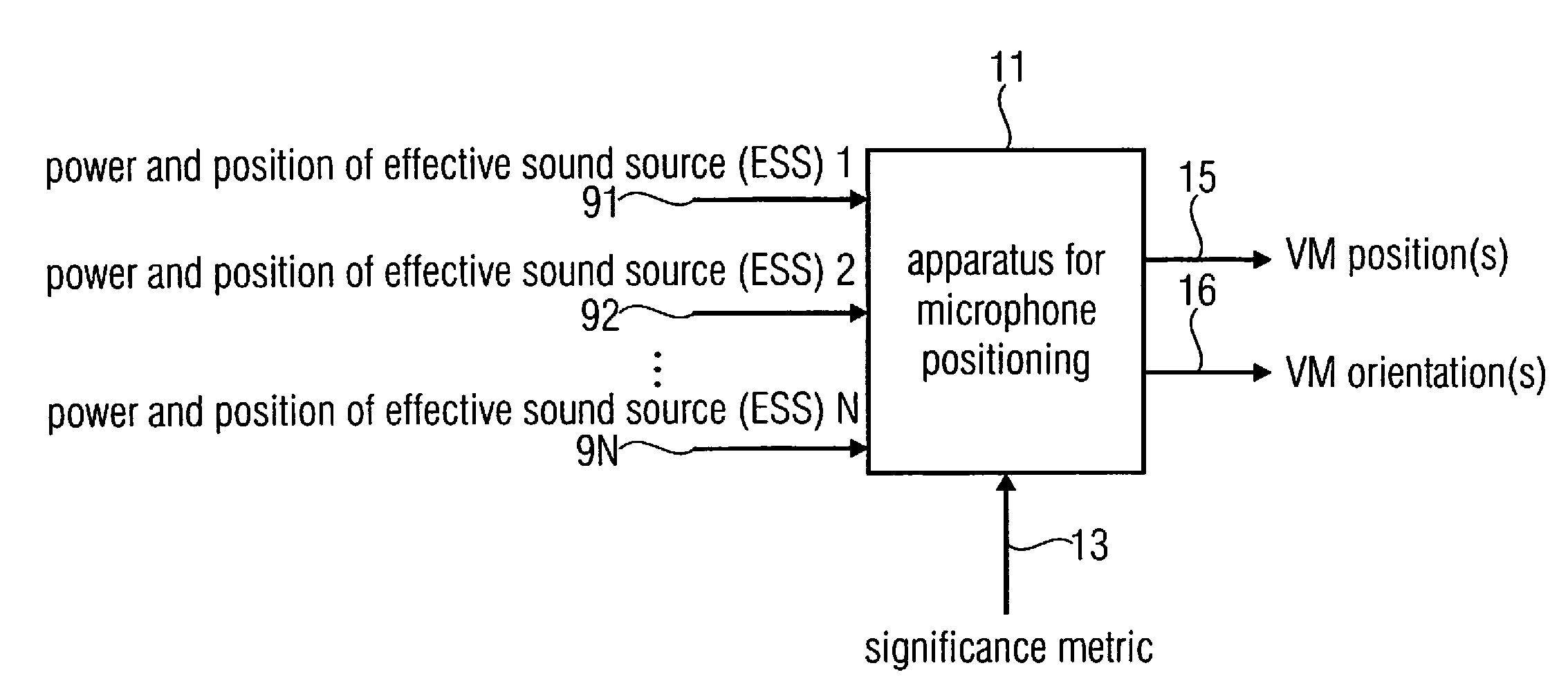
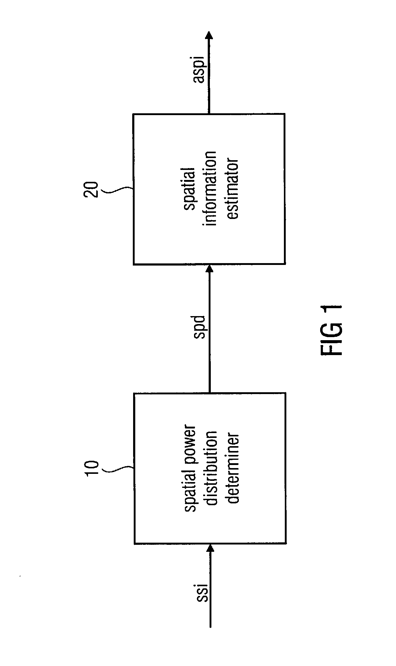
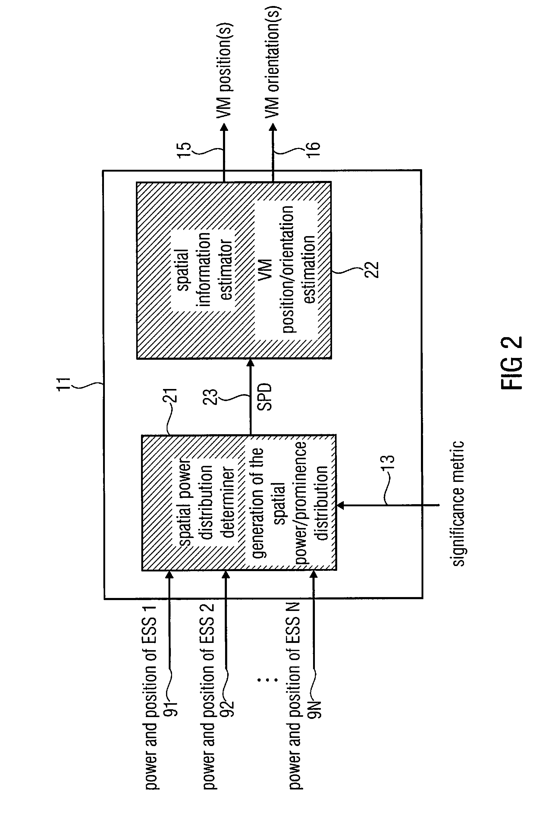
An apparatus for microphone positioning includes a spatial power distribution determiner and a spatial information estimator. The spatial power distribution determiner is adapted to determine a spatial power density indicating power values for a plurality of locations of an environment based on sound source information indicating one or more power values and one or more position values of one or more sound sources located in the environment. The spatial information estimator is adapted to estimate acoustic spatial information based on the spatial power density.
Description
CROSS-REFERENCE TO RELATED APPLICATIONS[0001]This application claims priority from European Patent Application No. EP11191828.0, which was filed on Dec. 2, 2011 and is incorporated herein in its entirety by reference.[0002]The present invention relates to audio signalprocessing and, in particular, an apparatus and a method for automatic microphone positioning.BACKGROUND OF THE INVENTION[0003]Audio signalprocessing becomes more and more important. In particular, spatial sound recording is employed in a plurality of applications. Spatial sound recording aims at capturing a sound field with the help of multiple microphones such that at the reproduction side, a listener perceives the sound image as it was at the recording location.[0004]Standard approaches for spatial sound recording usually involve spaced, omnidirectional microphones (e.g., AB stereophony) coincident directional microphones (e.g., in intensity stereophony), or more sophisticated microphones, such as a B-format microp...
Claims
Application Information
Patent Timeline
Application Date:The date an application was filed.
Publication Date:The date a patent or application was officially published.
First Publication Date:The earliest publication date of a patent with the same application number.
Issue Date:Publication date of the patent grant document.
PCT Entry Date:The Entry date of PCT National Phase.
Estimated Expiry Date:The statutory expiry date of a patent right according to the Patent Law, and it is the longest term of protection that the patent right can achieve without the termination of the patent right due to other reasons(Term extension factor has been taken into account ).
Invalid Date:Actual expiry date is based on effective date or publication date of legal transaction data of invalid patent.

