Method and apparatus for ultrasound phased array testing of bearing balls

a phased array and bearing ball technology, applied in the field of non-destructive evaluation of bearing balls, can solve the problems of ceramic bearing balls that are susceptible to defect-induced failure, conventional metal bearings are inappropriate, and most critical defects occur near the surface where the highest stress is produced, and achieve rapid surface inspection and low-cost detection of defects

Inactive Publication Date: 2009-01-22
UCHICAGO ARGONNE LLC
View PDF9 Cites 28 Cited by
  • Summary
  • Abstract
  • Description
  • Claims
  • Application Information

AI Technical Summary

Benefits of technology

The invention allows for quick and inexpensive detection of defects using surface acoustic waves or Rayleigh waves. The inspection can be done in less than one minute per ball.

Problems solved by technology

The technical problem addressed in this patent text is the need for a cost-effective non-destructive inspection system to detect any possible existing crack on bearing balls, which can lead to failure of the bearing system and potentially catastrophic results. The current methods are not effective and can result in inaccurate detection. The invention aims to provide an improved method and apparatus for ultrasonic phased array testing of bearing balls that overcomes the disadvantages of prior art arrangements.

Method used


Image

  • Method and apparatus for ultrasound phased array testing of bearing balls
  • Method and apparatus for ultrasound phased array testing of bearing balls
  • Method and apparatus for ultrasound phased array testing of bearing balls

Examples


Embodiment Construction

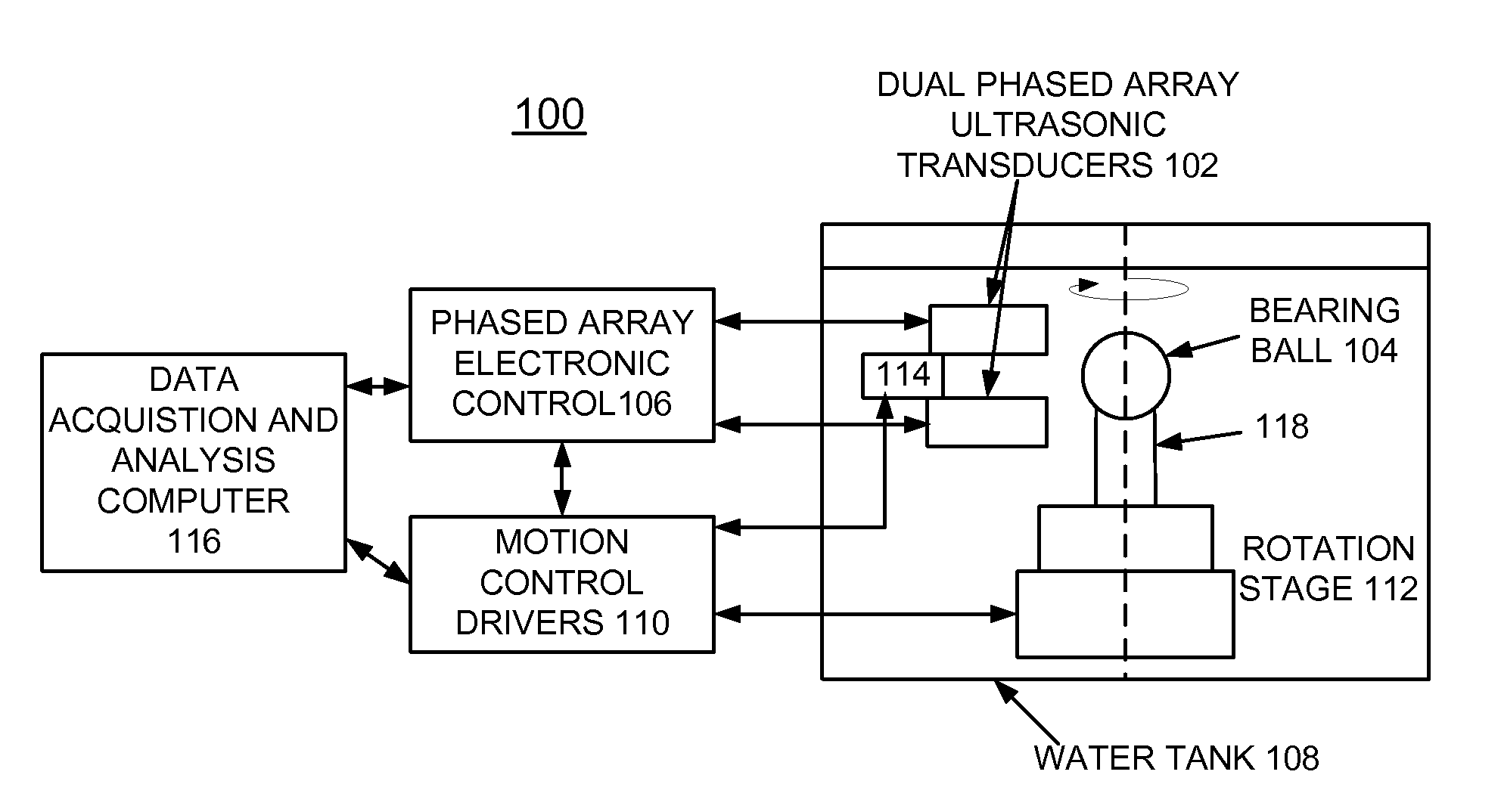
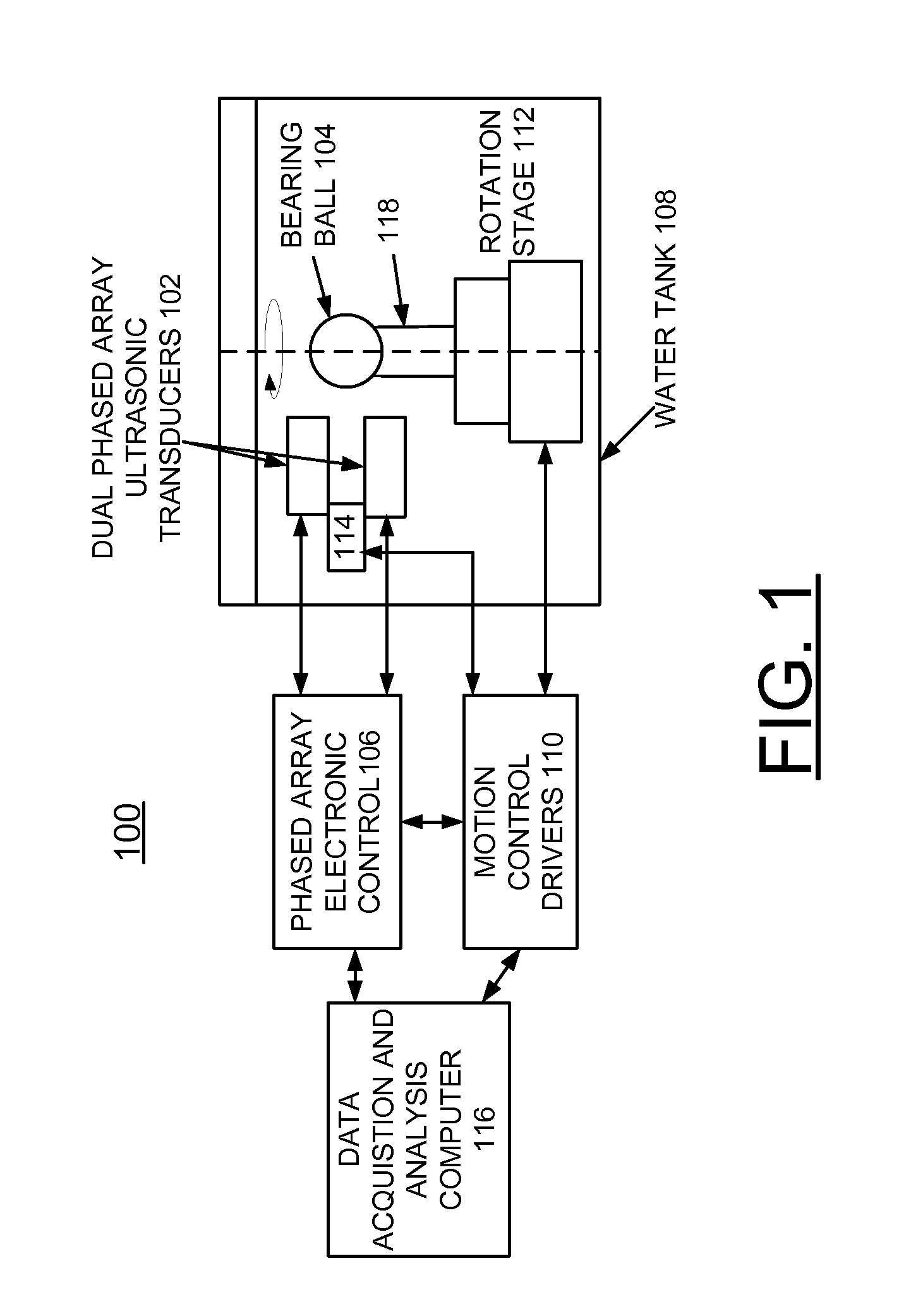
[0020]In accordance with features of the invention, a method and apparatus are provided for the nondestructive evaluation (NDE) of bearing balls. The invention provides a method and apparatus for the detection and characterization of surface breaking cracks in ceramic bearing balls. The invention overcomes limitations of prior art systems that utilize a very complex bearing ball handling mechanism and have a low signal to noise ratio which makes accurate C-crack detection difficult.

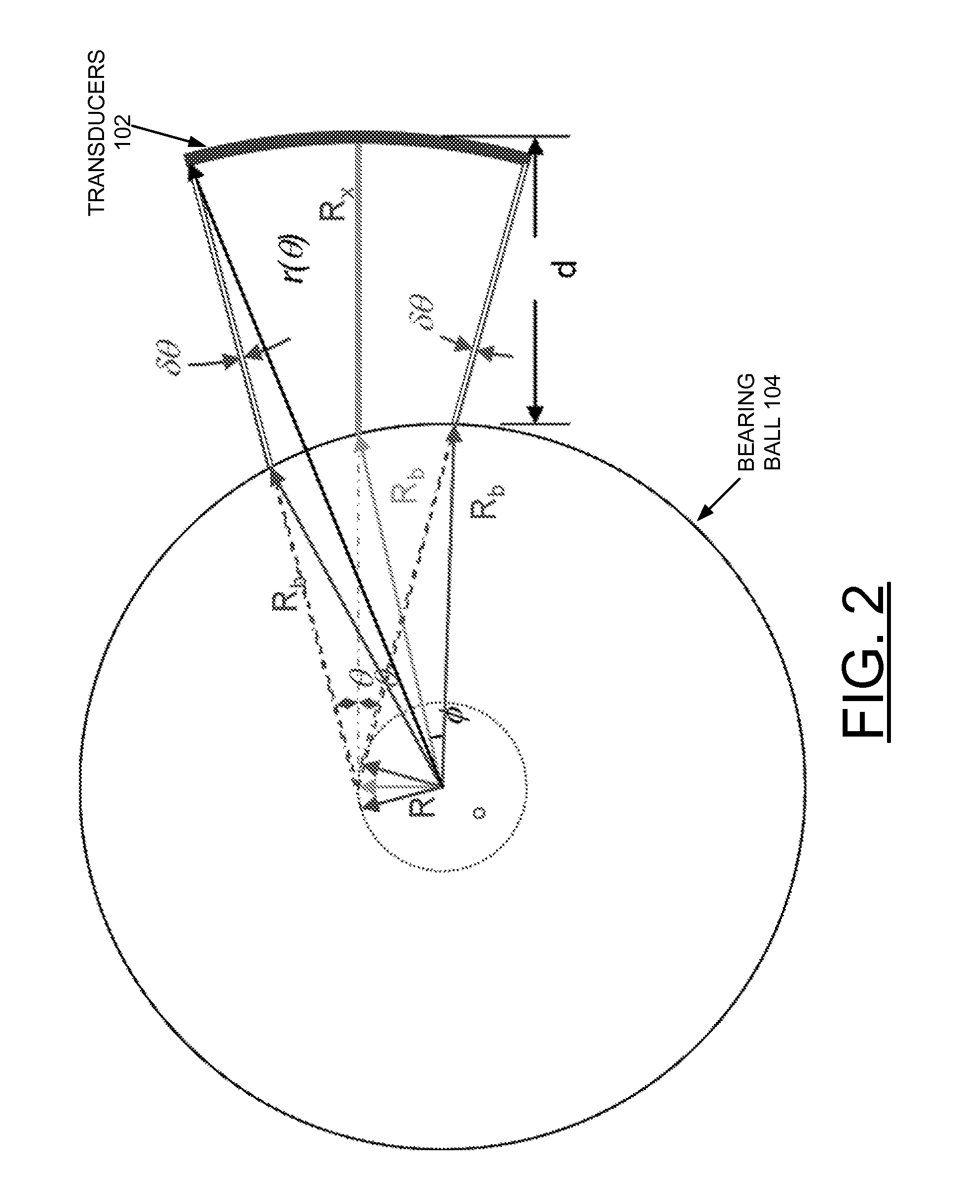
[0021]Ultrasonic surface acoustic waves, also called Rayleigh waves, are defined as a guided wave that propagates along the surface of a medium. Like other guided waves (such as Lamb waves), surface acoustic waves (SAWs) travel in the lateral direction, and propagate along the materials surface. Their use for NDE is a single-sided technique. This makes SAWs an attractive means of detecting defects that are perpendicular to a material's surface, such as surface breaking cracks. Surface acoustic waves are s...


PUM


Abstract

An automated scanning system and method, utilizing specialized dual phased array ultrasonic transducers for producing and detecting Rayleigh waves in ceramic bearing balls are provided for nondestructive, non-contact inspection of ceramic bearing balls. The phased array ultrasonic transducer utilizes a complex curvature configuration that enables the dual phased array ultrasonic transducers to focus ultrasonic energy onto the ball to optimally generate and receive Rayleigh wave signals in the spherical objects.

Description


Claims


Application Information

Patent Timeline
Owner UCHICAGO ARGONNE LLC
Why Eureka
Try Eureka