Eureka AIR delivers breakthrough ideas for toughest innovation challenges, trusted by R&D personnel around the world.

Frangible flapper valve with hydraulic impact sleeve

Active Publication Date: 2009-01-22
SUPERIOR ENERGY SERVICES LLC
View PDF3 Cites 29 Cited by
  • Summary
  • Abstract
  • Description
  • Claims
  • Application Information

AI Technical Summary

Benefits of technology

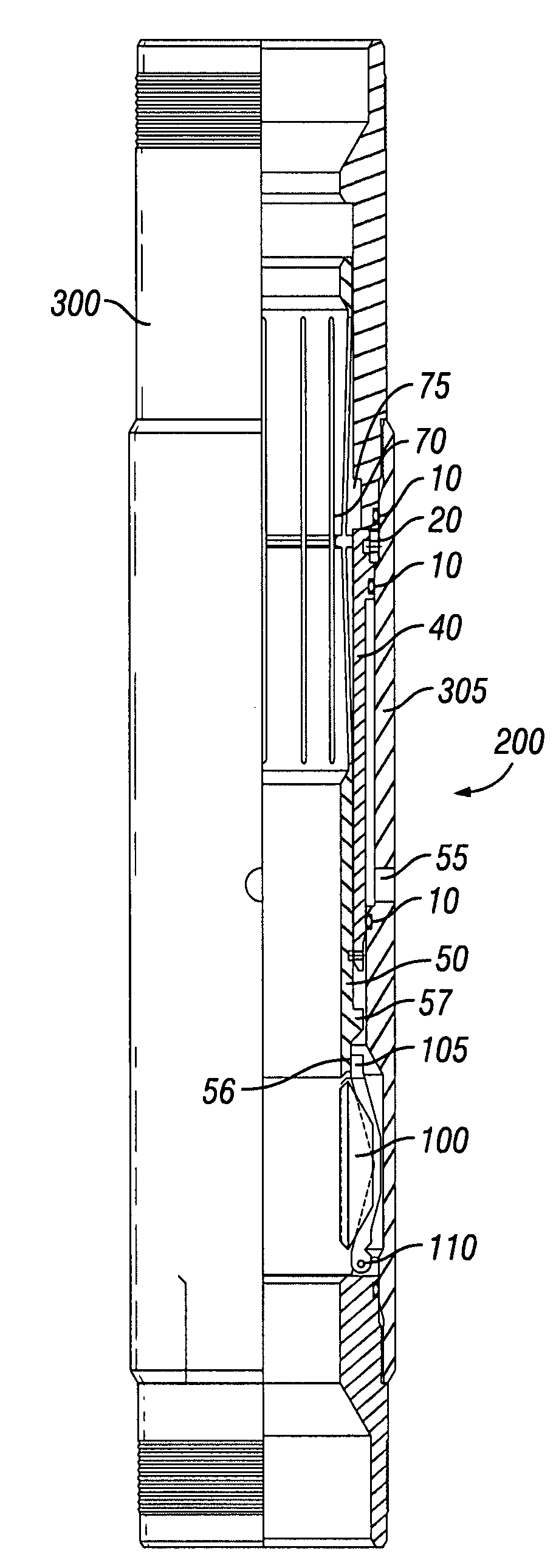
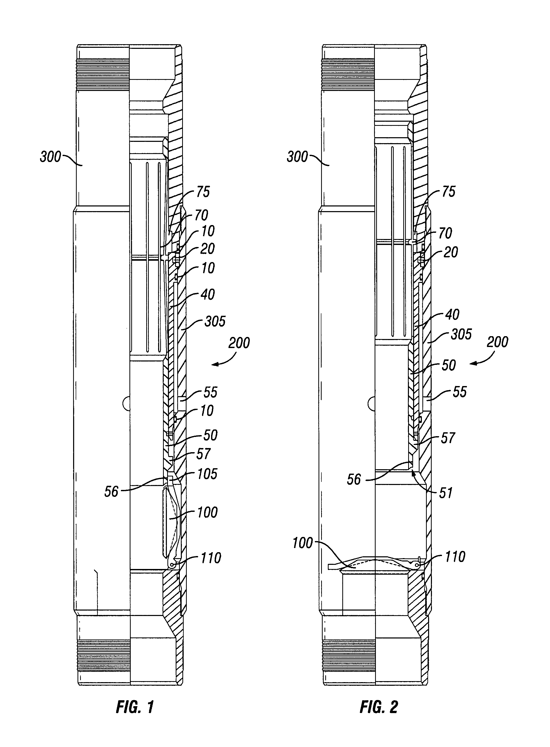
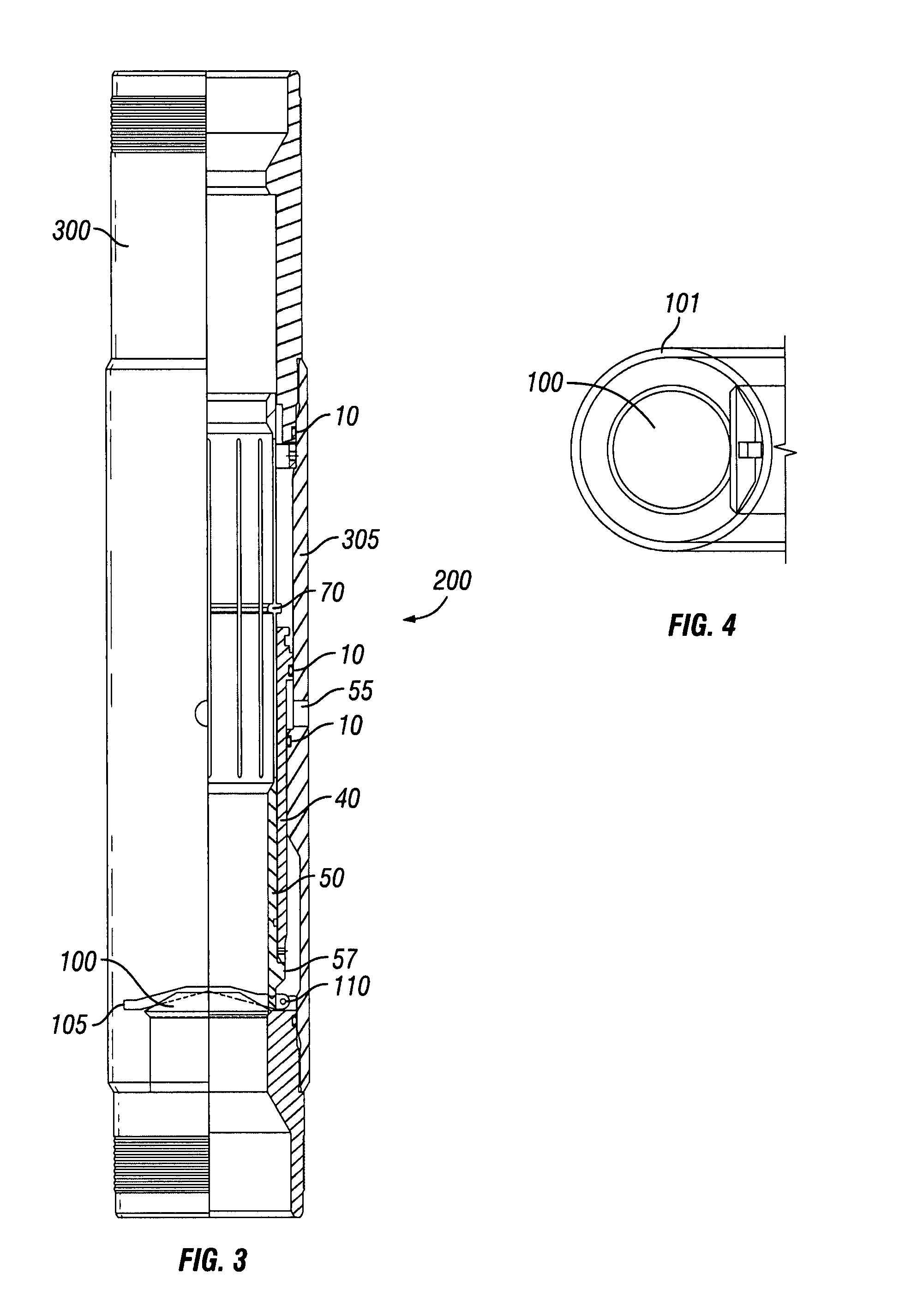
[0010]The object of the present disclosure is to provide a frangible flapper system that may be used to selectively isolate a portion of a wellbore tubular. One embodiment includes a tubular member, a flapper valve rotatably disposed within the tubular member being movable between an open position and a closed position, and an actuation assembly moveably disposed within the tubular member. The actuation assembly is movable between a first position, a second position, and a third

Problems solved by technology

The closed flapper may cause a high pressure differential to be created on the opposite sides of the closed flapper making it difficult to reopen.
Further, it may be difficult to grab a hold of the flapper with a tool to reopen the valve.
Other flapper valves have been designed to be operated hydraulically, which increases the complexity of the valve.
However, it is difficult to predict when and at what pressure such a flapper will break.

Method used


Image

  • Frangible flapper valve with hydraulic impact sleeve
  • Frangible flapper valve with hydraulic impact sleeve
  • Frangible flapper valve with hydraulic impact sleeve

Examples


Embodiment Construction

[0035]Illustrative embodiments of the invention are described below as they might be employed in a system and method that uses a frangible flapper valve to isolate a portion of a wellbore tubular and a hydraulic impact sleeve used to break the closed frangible flapper valve. In the interest of clarity, not all features of an actual implementation are described in this specification. It will of course be appreciated that in the development of any such actual embodiment, numerous implementation-specific decisions must be made to achieve the developers' specific goals, such as compliance with system-related and business-related constraints, which will vary from one implementation to another. Moreover, it will be appreciated that such a development effort might be complex and time-consuming, but would nevertheless be a routine undertaking for those of ordinary skill in the art having the benefit of this disclosure.

[0036]Further aspects and advantages of the various embodiments of the in...


PUM


Abstract

A frangible flapper valve that may be closed to hydraulically isolate a portion of a wellbore tubular. The flapper valve is made of a frangible material adapted to shatter upon impact from an impact sleeve. The sleeve may be used to initially hold open the flapper valve. A latching mechanism may be used to retain the sleeve above its initial position allowing the flapper to close isolating a portion of the tubular. The latching mechanism may engage a piston to retain the sleeve at the second position. A shearable device adapted to shear under a predetermined pressure selectively connects the piston to the tubular. When the pressure within the tubular increases above the predetermined amount the shearable device releases the piston and pushes the sleeve into the closed flapper valve causing the flapper valve to shatter. A second latching mechanism may prevent further movement of the sleeve.

Description

BACKGROUND OF THE INVENTION[0001]1. Field of the Invention[0002]The present invention generally relates to a flapper valve that may be used to hydraulically isolate a portion of a wellbore tubular, the flapper valve being made of a frangible material that may be broken with a hydraulic impact sleeve. The flapper is movable from an open position and a closed position and may be biased to the closed position. The flapper is comprised of a frangible material, such as ceramic, that is adapted to shatter upon impact by an impact sleeve. The pressure within the tubular above the closed flapper may encourage the flapper to shatter once a crack is made in the flapper valve by the impact sleeve.[0003]The impact sleeve may be used to initially hold open the flapper valve allowing fluid flow through the wellbore tubular. When it is desired to hydraulically isolate a portion of the wellbore tubular, the impact sleeve may be moved up the wellbore tubular to a second position allowing the flapper...

Claims


Application Information

Patent Timeline
IPC IPC(8): E21B34/00
CPCE21B2034/005E21B34/103E21B2200/05
Inventor ROSS, RICHARD J.LAFARGUE, RUSSELL
Owner SUPERIOR ENERGY SERVICES LLC
Why Eureka
Eureka Blog
Learn More