Damper with pressure-sensitive compression damping

a damping and pressure-sensitive technology, applied in the field of dampers, can solve the problems of affecting the effect the inability to react, the relative complexity and cost of the damping force,

Inactive Publication Date: 2008-05-20
FOX FACTORY
View PDF135 Cites 262 Cited by
  • Summary
  • Abstract
  • Description
  • Claims
  • Application Information

AI Technical Summary

Problems solved by technology

One drawback of this construction is that it is only capable of reacting to one specific condition, the application of the vehicle brakes.
Drawbacks of this construction include its relative complexity and cost, as well as blocked availability to the central passage down the piston rod, which could otherwise be utilized for inclusion of alternate pre-set adjustment mechanisms in communication with the damping piston.
One drawback of this construction is that it produces a relatively “flat” force vs. velocity compression damping curve (a “blow-off” type of damping characteristic), which can be difficult to tune for specific applications and conditions.

Method used


Image

  • Damper with pressure-sensitive compression damping
  • Damper with pressure-sensitive compression damping
  • Damper with pressure-sensitive compression damping

Examples


Embodiment Construction

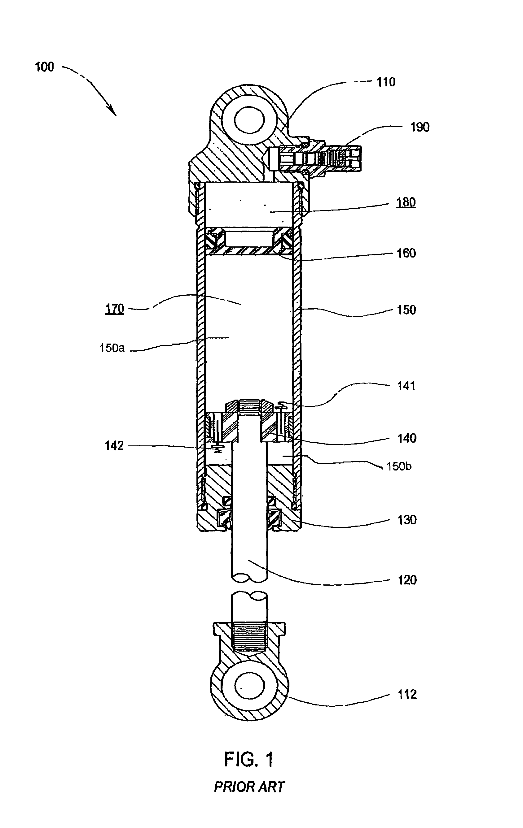
[0056]The prior-art damper 100 of FIG. 1 will be described first, in order to provide a point of departure for better understanding the improvements of the present invention, which will be described further on. It is to be understood, of course, that this specific prior-art embodiment is representative only, and that the embodiments disclosed herein may be applied to other types of dampers.

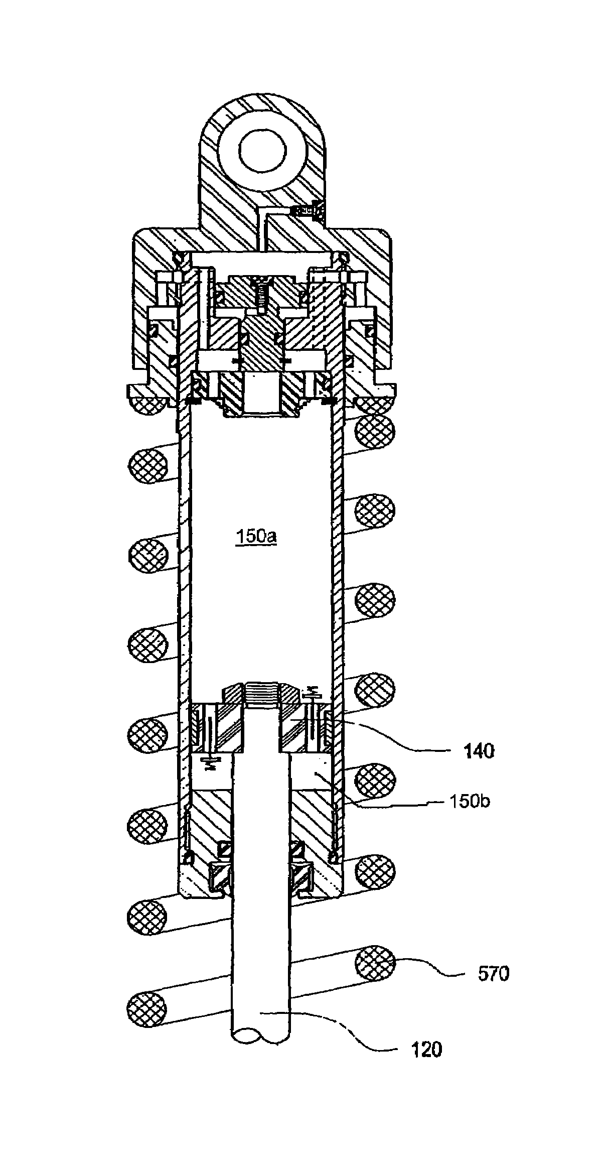
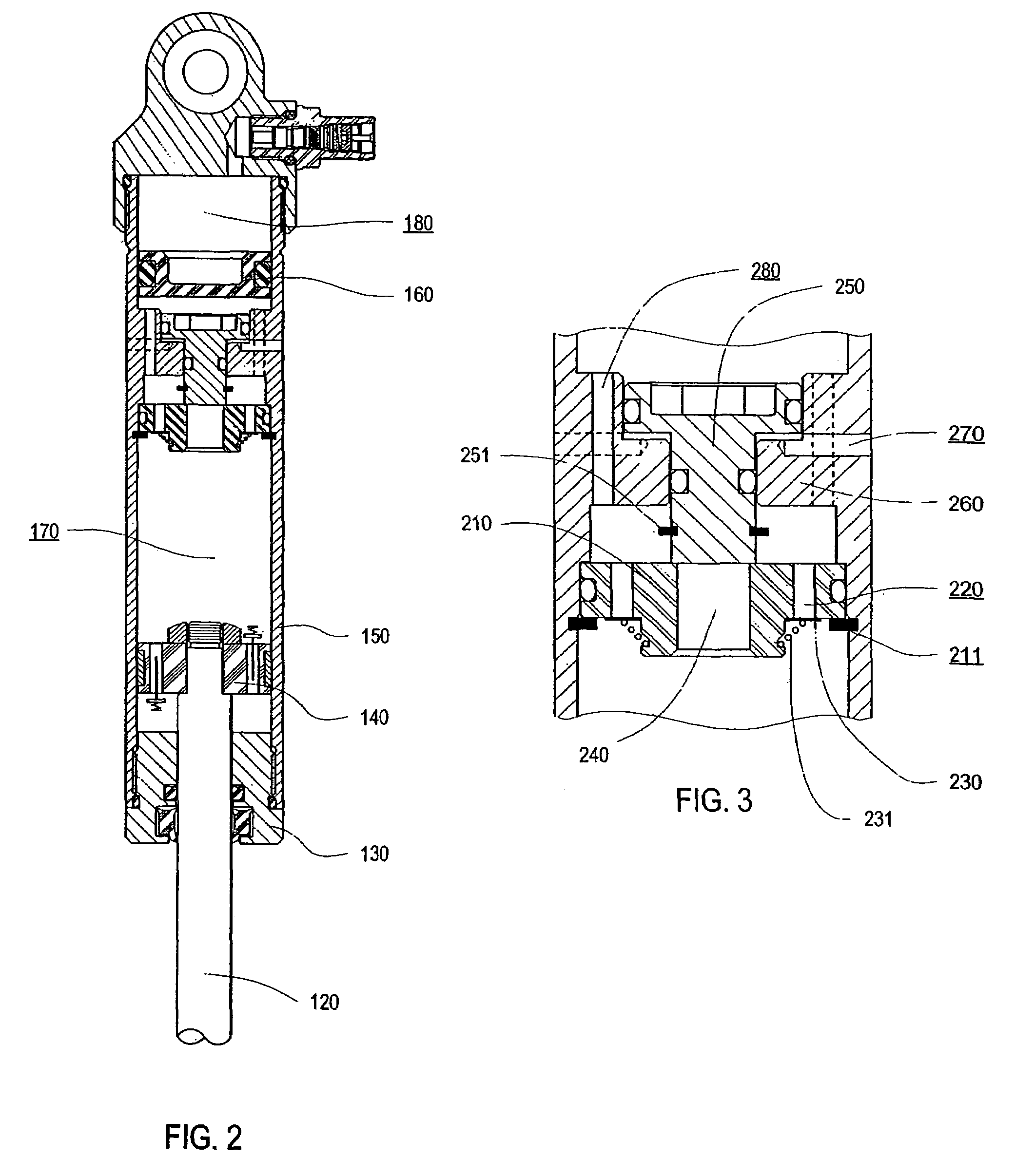
[0057]In FIG. 1 the prior-art damper 100, as is known to those skilled in the art, is comprised of an upper eyelet 110 and a lower eyelet 112 for attachment to, for example, the sprung and un-sprung portions of a vehicle (not shown). The lower eyelet 112 is connected to the piston rod 120 which passes through the seal head 130 and has a damping piston 140 attached at the other end. The damping piston 140 reciprocates in the damper cylinder 150 as the sprung and unsprung portions of the vehicle move relative to each other when, for example, the vehicle traverses uneven terrain. The damping piston 1...


PUM


Abstract

A self-pressurized damper, for example, a pressure-sensitive damper is described. At least one suspension spring is used to pressurize the damping fluid, a task typically carried out by a sealed moveable barrier, such as an internal floating piston (IFP) and a pressurized gas. Thus, stroke length may be maximized. Furthermore, the amount of compression damping force produced by the damper may be a function of the force generated by the at least one suspension spring.

Description

RELATED APPLICATIONS[0001]This application is a continuation of International Application No. PCT / US2004 / 038661, filed 18 Nov. 2004, which is a continuation of U.S. application Ser. No. 10 / 661,334 (now abandoned), filed 12 Sep. 2003, which claims priority to Provisional Application No. 60 / 485,485, filed 8 Jul. 2003, the entireties of which are hereby incorporated by reference herein and made a part of this specification.BACKGROUND OF INVENTION[0002]1. Field of Invention[0003]This invention relates to a damper and, more particularly, to a damper suitably used as a shock absorber or front fork on the suspension of a bicycle, motorcycle, automobile or other vehicle.[0004]2. Description of Related Art[0005]Dampers (shock absorbers, MacPherson struts, front forks, etc.) for controlling vehicle body motion and handling characteristics during vehicle travel over uneven surface are well-known in the art. Dampers typically comprise a closed hydraulic cylinder with an internal piston connecte...

Claims


Application Information

Patent Timeline
Patent Type & Authority Patents(United States)
IPC IPC(8): F16F9/34
CPCF16F9/512F16F9/44F16F9/5126
Inventor FOX, ROBERT C.
Owner FOX FACTORY
Why Eureka
Try Eureka