Vibration actuator having magnetic circuit elastically supported by a spiral damper with increased compliance

a technology of elastic support and vibration actuator, which is applied in the direction of magnets, magnetic bodies, transducer diaphragms, etc., can solve the problems of difficult damper production, large radial stiffness, and difficulty in producing dampers, so as to improve shock resistance, maintain stable characteristics, and high reliability

Inactive Publication Date: 2002-04-23
TOKIN CORP
View PDF6 Cites 82 Cited by
  • Summary
  • Abstract
  • Description
  • Claims
  • Application Information

AI Technical Summary

Benefits of technology

It is therefore an object of the present invention to provide a vibration actuator which is capable of improving a shock resistance to keep stable characteristics and high reliability over a long period of time.

Problems solved by technology

The effective angle has been usually selected to be an angle smaller than 55 angular degrees, considering that use of a large effective angle makes it difficult to produce the damper.
However, the above-mentioned existing vibration actuator is disadvantageous in that the damper may often suffer a permanent strain if an abnormal stress is applied by external shock or the like.
After studying the reason of the problem caused, the inventor knew that the existing damper having spiral spring portions with the effective angle smaller than 55 angular degrees cannot provide a sufficient high compliance against any relatively large external force caused due to mechanical shock such as dropping but still exhibits a relatively large stiffness in the radial direction.
If subjected to such a large external stress, for example, when the vibration actuator is dropped, the magnetic circuit may abnormally be displaced in the radial direction.
Such abnormal displacement may leave the permanent strain in the damper and may further cause the inclination of the center shaft of the magnetic circuit.
In case where the strain or the inclination is great, the abnormal stress is applied to the damper so that the stability in characteristics would be deteriorated.

Method used


Image

  • Vibration actuator having magnetic circuit elastically supported by a spiral damper with increased compliance
  • Vibration actuator having magnetic circuit elastically supported by a spiral damper with increased compliance
  • Vibration actuator having magnetic circuit elastically supported by a spiral damper with increased compliance

Examples


Embodiment Construction

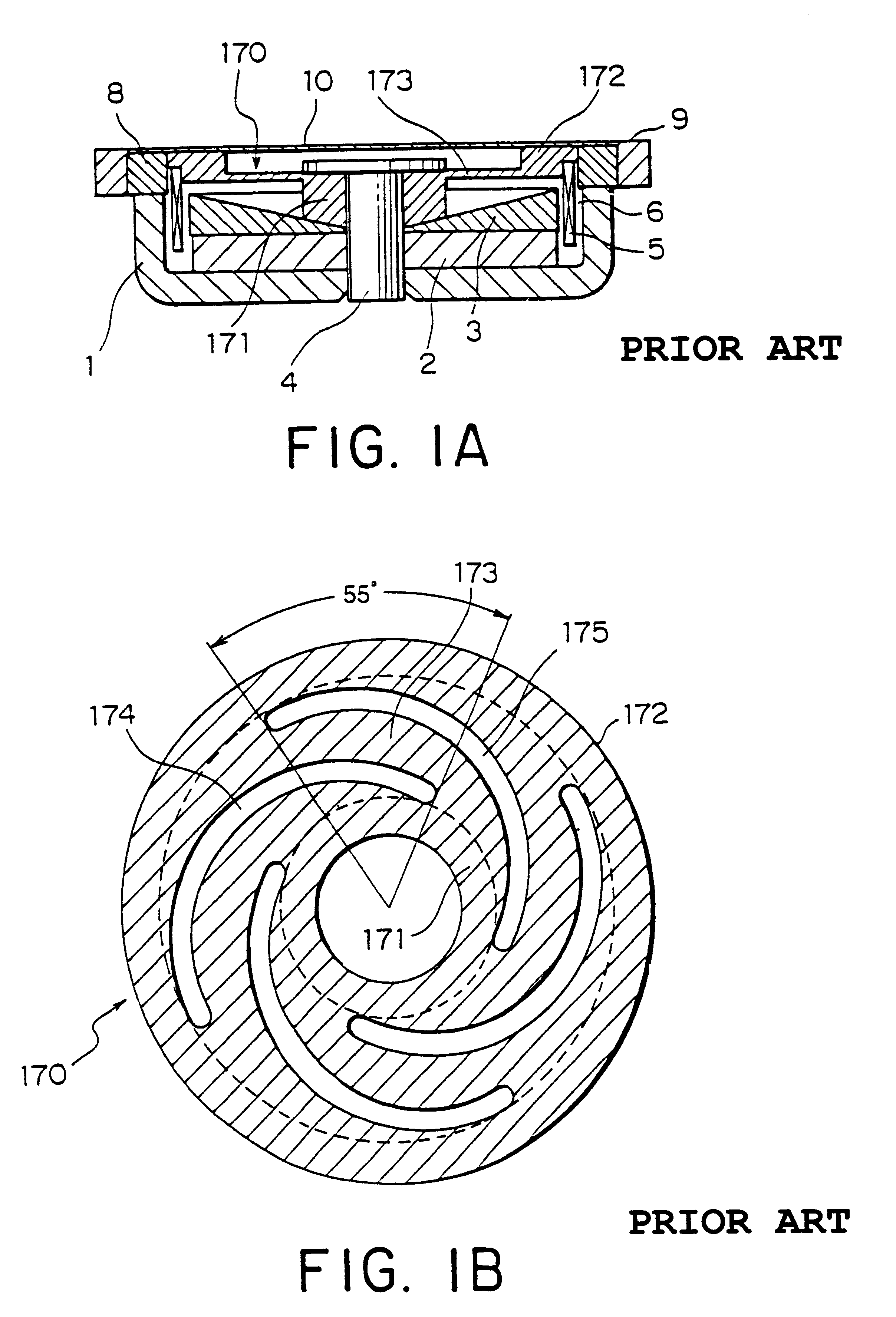
Prior to description of preferred embodiments of this invention, an existing vibration actuator will be described with reference to FIGS. 1A and 1B, so as to facilitate understanding of this invention.

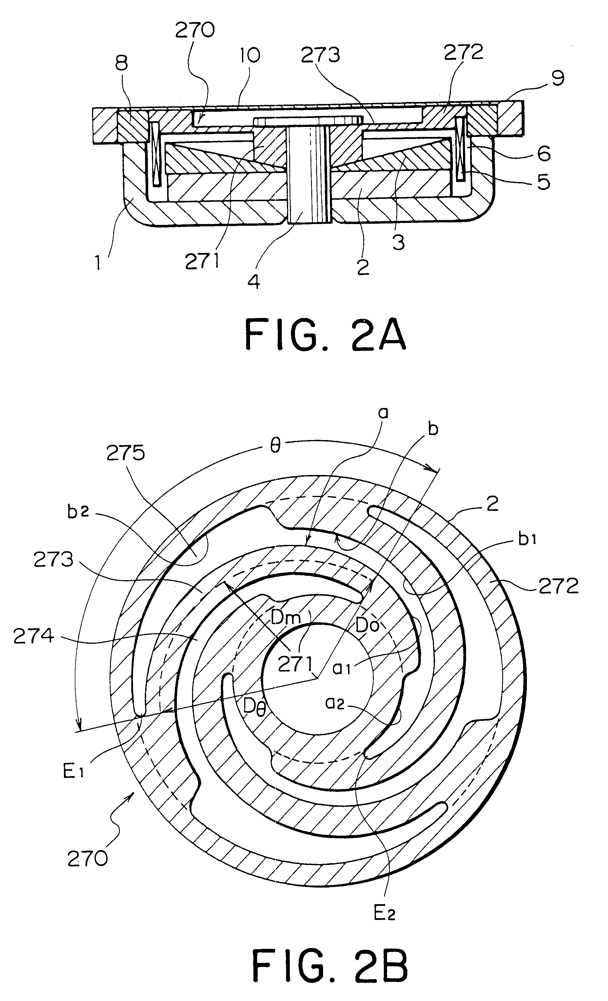
Referring to FIG. 1A, the vibration actuator shown therein has an electro-mechanical transducer of the electro-dynamic type and has a cylindrical shape with a center shaft 4. Around the center shaft 4, a magnetic circuit is formed by a yoke 1 having a peripheral side wall, a plate 3 arranged inside the yoke 1, and a disk-shaped permanent magnet 2 interposed between the yoke 1 and the plate 3. The permanent magnet 2 and the plate 3 are surrounded by the peripheral side wall of the yoke 1 and a magnetic gap is 6 left therebetween. A driving coil or moving coil 5 is disposed in the magnetic gap 6.

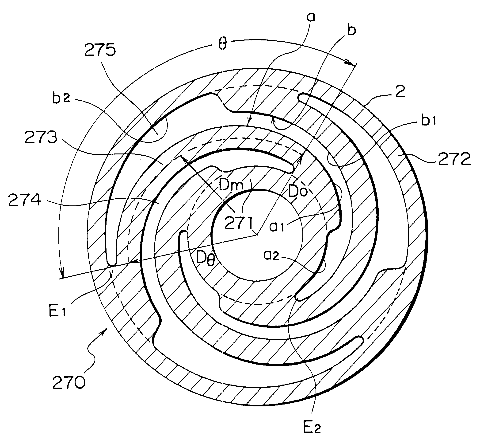
A disk-shape damper 170 supports the magnetic circuit 1-4 on a support frame 9. The damper 170 comprises an inner ring portion 171, an outer ring portion 172 and a plurality of spiral spring port...


PUM

PropertyMeasurementUnit
outer diameteraaaaaaaaaa
heightaaaaaaaaaa
weightaaaaaaaaaa

Abstract

A vibration actuator includes an electromechanical transducer having a magnetic circuit (1-4) and a driving coil (5), a support frame (9), and a damper (270) elastically supporting the magnetic circuit onto the support frame to flexibly damp the vibration of the magnetic circuit when a driving AC current is supplied to the coil (5). The damper (270) comprises inner and outer ring portions (271, 272) and a plurality of spiral spring portions (273) determined by a plurality of spiral slits (274, 275) formed in the damper. In order to reduce the spiral spring portion determined by the adjacent two spiral slits in its compliance, each of the spiral spring portions has an effective spring length determined by an effective angle (theta) which is determined as an angle (by angular degree) from an inner end of the inner spiral slit to an outer end of the outer spiral slit defining each respective spiral spring portion around a center of the damper. The effective angle is 55 angular degree or more. In a preferable example, the effective spring length is determined by a product (r.theta) of an average radius (r) value by the unit of "mm" and the effective angle (theta) value by unit of the angular degree. The effective spring length is selected to 320 or more, and preferably 400 or more.

Description

This invention relates to a vibration actuator using an electro-mechanical transducer including a magnetic circuit and a driving coil and having a damper elastically supporting the magnetic circuit, and in particular to a structure of the damper.An electro-dynamic type of the electromechanical transducer comprises a magnetic circuit comprising a magnet and magnetic yoke and having a magnetic gap therein, and a moving coil or ribbon disposed in the magnetic gap. When a driving AC current is applied to the moving coil or ribbon, the moving coil or ribbon vibrates relatively to the magnetic circuit. A frequency of the vibration is dependent on a frequency of the driving AC current. Since the moving coil or ribbon is applied with the driving AC current and moves or vibrates, it is referred to as a driving coil and also a moving element.When the driving AC current is of an audio frequency, the moving coil or ribbon vibrates at the audio frequency. When a thin plate or diaphragm is connec...

Claims


Application Information

Patent Timeline
Patent Type & Authority Patents(United States)
IPC IPC(8): H04R7/16H04R7/00H04R9/02H04R9/00
CPCH04R7/16H04R2400/07H04R9/025
Inventor KUMAGAI, TORU
Owner TOKIN CORP
Why Eureka
Try Eureka