[0002] In the
electric field, nonlinear loads, dynamic loads or unbalanced sources are the common working environments, for example, the electric vehicles,
hybrid power vehicles as disclosed in Chapter 4 of [43] (please refer to Appendix I), the CD-ROMs as disclosed in [48], [47] and Chapter 6 of [50], high-power devices, and so on. However, to perform dynamic
impedance matching to nonlinear loads is very difficult. Take the system shown in FIG. 47 for example, if only Load1 4701, Load2 4702 and Load3 4703 exist in the system originally, and then a new load(s) 4704 is added into the system, the
total impedance of the system would suddenly change, and disadvantageous effects such as
electric arc and power waveform distortions would possibly occur.
[0003] In an electrical power system, the nonlinearity comes from switching on / off actions and reactions when power
converters (such as AC-to-DC
converters, DC-to-DC
converters, DC-to-AC converters, and AC-to-AC converters, referring to [80], [53] and Chapters 5-7 of [62]) are used. The nonlinearity brings into power waveform distortions such as harmonic and sub-harmonic distortions as discussed in Appendix E. How to remove the distorted power waveforms becomes a very important issue. Many researches (as disclosed in [72], [41], [62], [58], [52], [39], [8], [33], [59], [21], [16], and [15]) try to find practical ways to deal with these
complex problems. However, since power sources are polluted by the harmonic, sub-harmonic or inter-harmonic distorted power waveforms contributed by
inverter-base, switching-mode power driving devices or nonlinear loads / sources, according to the references [62], [53], [25], [54], [55] and [56], it is impossible for conventional techniques to clean the distorted power waveforms out entirely to obtain the best
power quality.
[0004] The nonlinearity comes from the duality of an electric system. As shown in FIG. 4 (referring to Page 56 of [5] and Chapter 6 of [43]), when IGBT1 (Integrated Gate Bipolar
Transistor) 401 and IGBT4 402 are turned on at the same time, the current from point R 403 passing through coils Φ1 406 and Φ2 407 and then returning to point S 404 forms a loop. As IGBT1 401 and IGBT4 402 are turned off simultaneously, the current from S 404 immediately returns backward to the
DC bus through the R 403 and via the dissipative
diode D1 409, wherein the returning current will result in a conflicting
voltage that will modify the VDC. At the next stage, when IGBT3 410 and IGBT6 411 are turned on, the modified
voltage VDC is applied to a loop from point S 404 via coils Φ2 407 and Φ3 408 to point T 405; and when the IGBT3 410 and IGBT6 411 are turned off simultaneously, a returning
voltage will modify the modified VDC again. Therefore, the voltage VDC will be modified many times by returning EMF (
Electromotive Force). For a
heavy load system, such as a high-power
Electric Vehicle, this duality phenomenon will cause power interference (or (sub)harmonic
distortion waveforms) at each phase, which results in high temperature occurring at the six IGBTs, diodes and the coils Φ1 406, Φ2 407 and Φ3 408, and thus the system may be damaged.
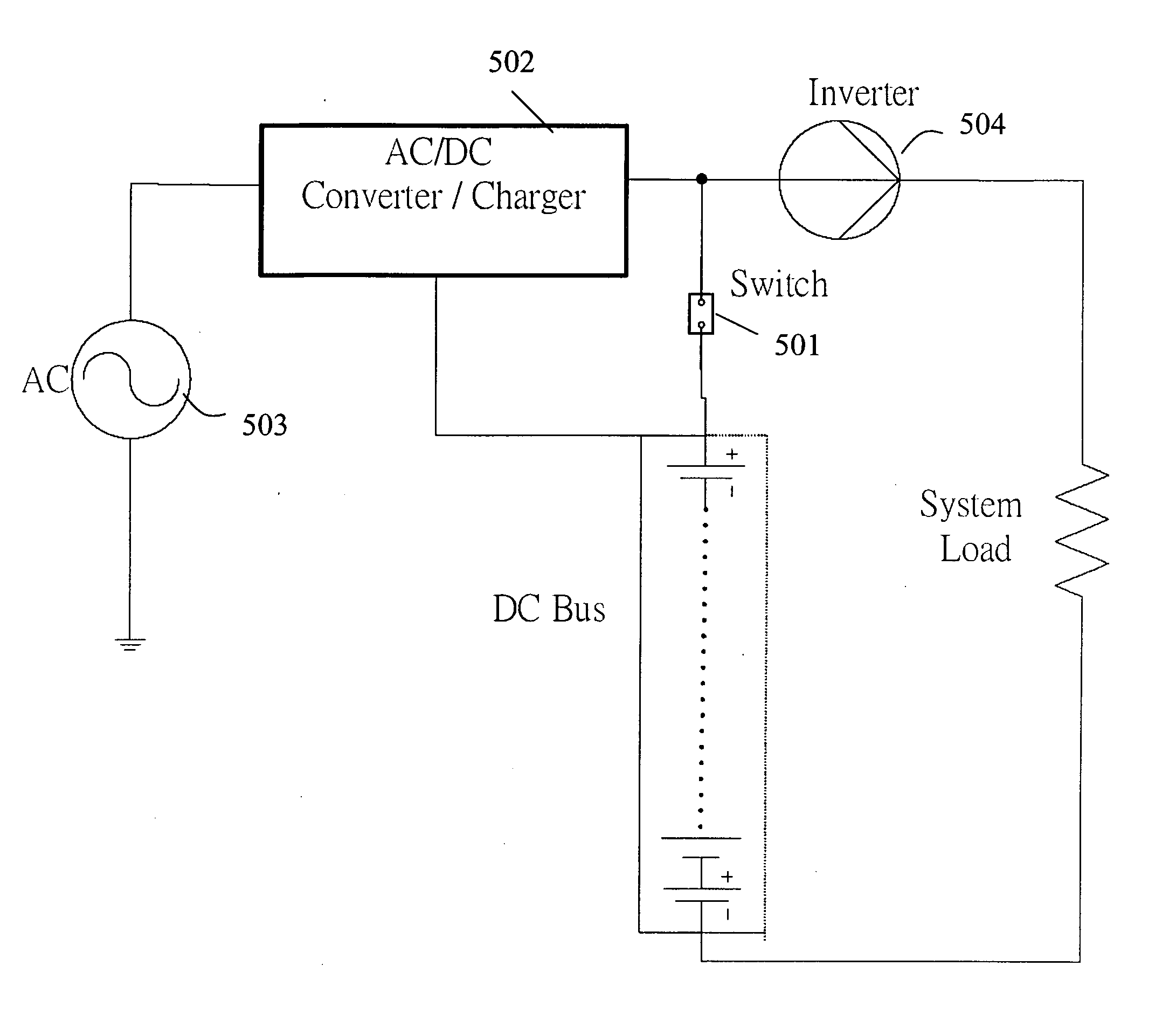
[0005] A common troublesome problem is the DC charger pump that works with low performance and produces a number of heat sources. For each phase, it is expressed in the form of VDC-e=Lⅆiⅆt+R i during phase-on period and in the form of -VDC-e=Lⅆiⅆt+Ri during phase-off period, wherein L, e, i, R are the corresponding
inductance, returning EMF, current and system resistance, respectively, and e>0. If it is under the condition of heavy loads, e will be greater than VDC and its current i will increase even during phase-off period. This regenerated power source will seriously affect system reliability and create high
operating temperature.
[0006] According to prior art references (Vol. 2 Chapter 8, 9, 10, 11, 22, 23 of [74], Page 173 of [24] and Page 181 of [5]), although to construct an order-k resonant tank is complex, it is still possible as long as k is a finite number as follows: 0<k<M where M is a positive constant. An order-k resonant tank can be constructed based on the circuit shown in FIG. 46. According to Thevenin's theorem and Norton's theorem, the circuit shown in FIG. 46 is totally equivalent to a specific mode with specific Ce, Le, and resonant frequency ωr=1LeCe. If k switches S1, S2, . . . , Sk are added to the circuit shown in FIG. 46, we can obtain an order-k resonant tank, wherein each mode of the order-k resonant tank can be obtained by turning on / off corresponding switches.
[0007] In practice, there exists much more complex interactions between nonlinear loads and power supplies in an electrical power system, and a finite-order resonant tank does not fully match to the system. Therefore, to construct an order-∞ resonant tank is desired for a long time. If the idea of constructing an order-k resonant tank is extended to that of an order-∞ resonant tank,
infinite number of inductors, capacitors, and switches should exist and be electrically interconnected. Obviously, it is impossible to construct an order-∞ resonant tank based on the fundamental circuit shown in FIG. 46. SUMMARY OF THE INVENTION

