Cascade megawatt photovoltaic grid-connected inverter
A megawatt-level inverter technology is applied in the topology structure field of cascaded megawatt-level photovoltaic grid-connected inverters. Low stress, low switching loss and high energy conversion efficiency
Inactive Publication Date: 2011-06-15
SOUTHEAST UNIV
View PDF1 Cites 44 Cited by
- Summary
- Abstract
- Description
- Claims
- Application Information
AI Technical Summary
Problems solved by technology
However, the addition of power frequency transformers affects the volume, weight, cost and efficiency of the entire inverter equipment
Method used
View moreImage
Smart ImageViewing Examples
Examples
Embodiment Construction
Login to View More PUM
 Abstract
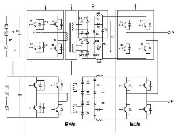
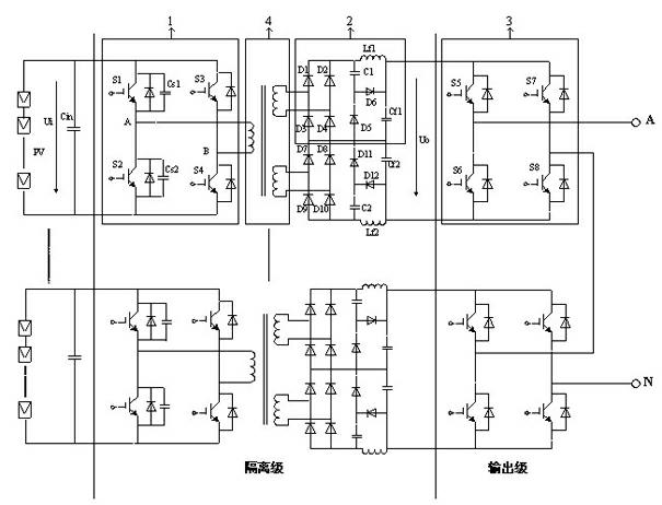
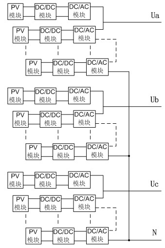
The invention provides a cascade megawatt photovoltaic grid-connected inverter, wherein a topology structure of the cascade megawatt photovoltaic grid-connected inverter is composed of two levels, namely a DC / DC (direct current / direct current) isolation level and a DC / AC (direct current / alternating current) output level; the structures of three phases of circuits are the same; the output ends of a power inverter group of each single-phase of DC / DC output level are connected in a star shape; the input sides of power units of each single-phase level are provided with independent PV (photovoltaic) modules of the same structure; the DC / DC isolation level comprises high-frequency DC / AC, a high-frequency transformer and high-frequency AC / DC nodes of each single-phase for realizing isolation and boosting, and reducing the consumption of a switch tube via action of a resonant soft switch; the output level power transformer set adopts a bridge type inverter circuit; and the single-phase output level power units are connected with each other in a cascade mode. Based output cascade, the device can realize megawatt grid connection; as a high-frequency chain technology is used, the traditional low frequency transformer is omitted, and the power density is high; and compared with the existing photovoltaic grid-connected inverter structure, the device provided by the invention has the advantages of high energy conversion efficiency, excellent output energy quality, certain fault-tolerant capability and the like.
Description
Cascaded megawatt-level photovoltaic grid-connected inverter technical field The patent of the invention relates to a topology structure of a cascaded megawatt-level photovoltaic grid-connected inverter, which belongs to the technical field of application of power electronics in power systems. Background technique Due to the depletion of traditional energy sources and the increasingly prominent environmental protection issues, the development and utilization of new energy sources are becoming more and more important. Among them, solar energy is favored for its economical and clean characteristics. Since the 21st century, the world's solar photovoltaic power generation industry has developed rapidly, and China's photovoltaic industry has also developed rapidly at an unprecedented speed. Now "new energy" and "energy saving and emission reduction" have become an important direction of national economic development, adding vitality to the development of photovoltaic power gene...
Claims
Login to View More Application Information
Patent Timeline
 Patent Type & Authority Applications(China)
IPC IPC(8): H02M7/48H02M3/335H02M7/5387
CPCY02E10/56
Inventor 赵剑锋王书征施超邵楚雯刘晓康晏阳
Owner SOUTHEAST UNIV
Features
- R&D
- Intellectual Property
- Life Sciences
- Materials
- Tech Scout
- Unparalleled Data Quality
- Higher Quality Content
- 60% Fewer Hallucinations
Learn More Browse by: Latest US Patents, China's latest patents, Technical Efficacy Thesaurus, Application Domain, Technology Topic, Popular Technical Reports.
© 2025 PatSnap. All rights reserved.Legal|Privacy policy|Modern Slavery Act Transparency Statement|Sitemap|About US| Contact US: help@patsnap.com


