Electroactive polymer devices for moving fluid

a technology of moving fluid and electroactive polymer, which is applied in the direction of device details, non-mechanical valves, oscillatory slide valves, etc., can solve the problems of complex mechanical structure, high cost, inefficiency, etc., and achieve the effect of improving the mechanical response of electroactive polymer

Inactive Publication Date: 2006-06-20
SRI INTERNATIONAL
View PDF77 Cites 253 Cited by
  • Summary
  • Abstract
  • Description
  • Claims
  • Application Information

AI Technical Summary

Benefits of technology

[0034]In other embodiments, the polymer may comprise a material selected from the group consisting of a silicone elastomer, an acrylic elastomer, a polyurethane, a copolymer comprising PVDF, and combinations thereof. The device may include an insulation barrier designed or configured to protect the one surface from constituents of the fluid in contact with the one surface or one or more support structures de

Problems solved by technology

Conventional pumps and compressors are predominantly piston-driven with an electric motor; these conventional devices tend to be heavy (bulky), noisy, inefficient at slow speeds (or require gearboxes to step down higher speeds),

Method used


Image

  • Electroactive polymer devices for moving fluid
  • Electroactive polymer devices for moving fluid
  • Electroactive polymer devices for moving fluid

Examples


second embodiment

[0105]FIG. 2F, a bellows pump 315 is illustrated. The bellows pump includes a bladder 312 designed to fold in an accordion like manner when compressed. The bladder 312 is mounted between two support plates 303. A fluid conduit 314 passes through each of the support plates 303. The fluid conduits 314 include two check valves 316 that force the fluid to flow in the direction indicated by the arrows. The support plates are 303 are connected via a plurality of EPAM transducers 302. The bladder 312 is surrounding by a force return mechanism 311, such as a coil spring.

[0106]When energy is supplied to the EPAM transducers 302, the EPAM transducers 302 extend in length and the bladder 312 increases in volume drawing fluid into the bladder and lengthening the coil spring 311. When energy is removed or decreased to the EPAM transducers 302, the EPAM transducers contract and the support plates may be pulled together by the coil spring, reducing the volume of the bladder 312 and expelling fluid...

first embodiment

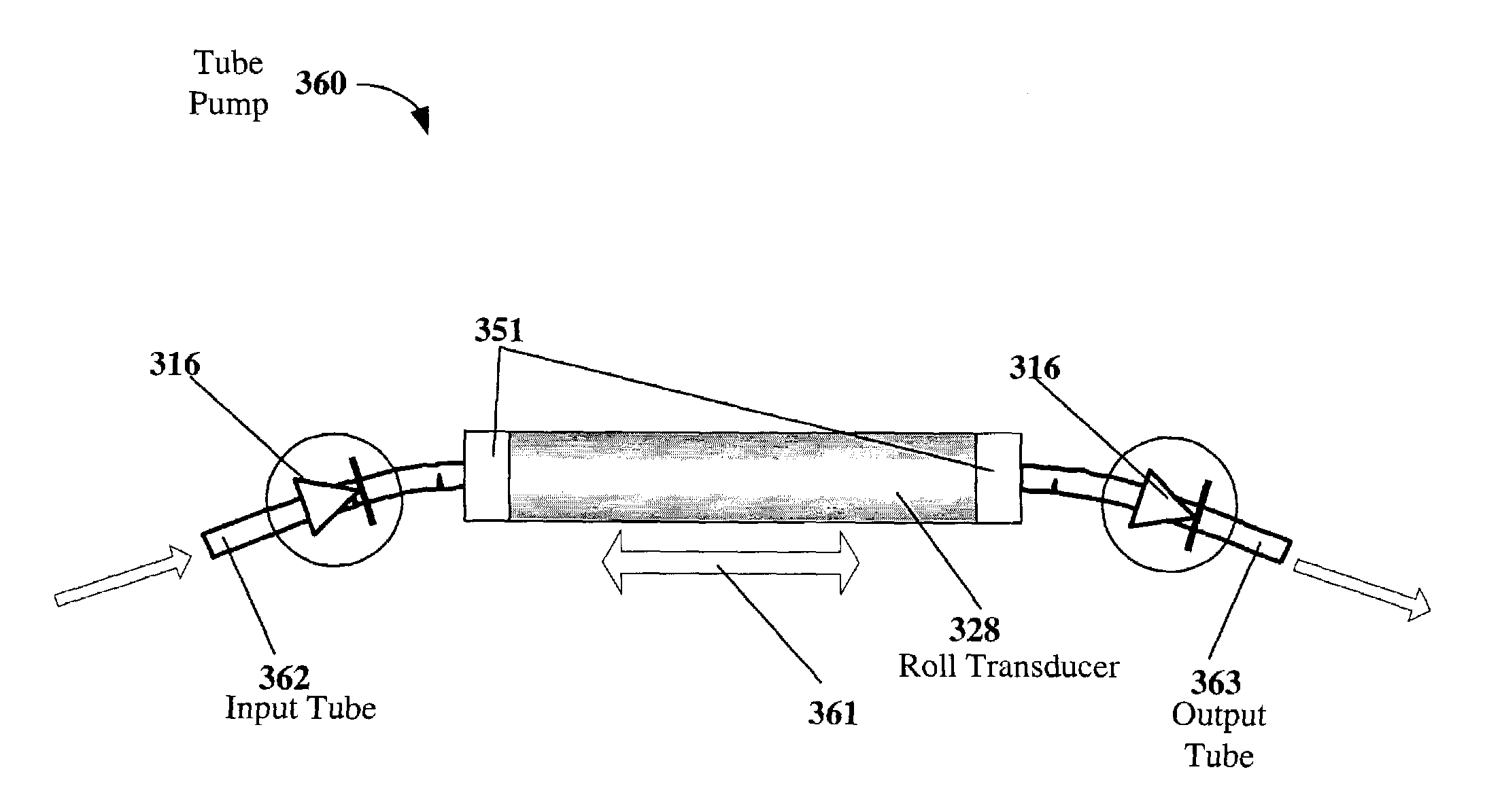
[0128]FIGS. 3A and 3B illustrate an EPAM tube-type pump device 350. The tube pumping device may comprise one or more electroactive polymer transducers. The pump can be made using one or more rolls of electroactive polymer (EPAM) film arranged in a roll transducer 352. The EPAM film may or may not be pre-strained.

[0129]By way of an example, FIG. 3A shows a cross-sectional view of an EP tube-type pump 350 where a tube of electroactive polymer is attached at both ends on rigid end structures 351. The tube can be made by rolling EPAM or made directly using dip coating processes. In a preferred embodiment, the EP tube is stretched axially to provide high pre-strain in the axial direction. The forces of pre-strain are supported by rigid rods 395 attached to the end structures on the outside or inside of the tube. With high pre-strain, the diameter of the tube will be contracted in the central portion due to Poisson contraction (not shown in FIG. 3A). Two one-way (check) valves 316 are att...


PUM

PropertyMeasurementUnit
Elastic modulusaaaaaaaaaa
Volumeaaaaaaaaaa

Abstract

The invention describes devices for performing thermodynamic work on a fluid, such as pumps, compressors and fans. The thermodynamic work may be used to provide a driving force for moving the fluid. Work performed on the fluid may be transmitted to other devices, such as a piston in a hydraulic actuation device. The devices may include one or more electroactive polymer transducers with an electroactive polymer that deflects in response to an application of an electric field. The electroactive polymer may be in contact with a fluid where the deflection of the electroactive polymer may be used to perform thermodynamic work on the fluid. The devices may be designed to efficiently operate at a plurality of operating conditions, such as operating conditions that produce an acoustic signal above or below the human hearing range. The devices may be used in thermal control systems, such as refrigeration system, cooling systems and heating systems.

Description

CROSS-REFERENCE TO RELATED APPLICATION[0001]This application claims priority under 35 U.S.C. §119(e) from co-pending; U.S. Provisional Patent Application No. 60 / 365,472, by Pelrine, et al., “Electroactive Polymer Devices For Moving Fluid,” filed Mar. 18, 2002 which is incorporated by reference for all purposes;[0002]and the application is a continuation-in-part and claims priority from U.S. patent application Ser. No. 09 / 792,431 entitled “Electroactive Polymer Thermal Electric Generators,” filed Feb. 23, 2001 now U.S. Pat. No. 6,628,040, which is incorporated herein by reference in its entirety for all purposes which claims priority under 35 U.S.C. §119(e) from U.S. Provisional Patent Application No. 60 / 184,217 filed Feb. 23, 2000, naming Q. Pei et al. as inventors, and titled “Electroelastomers And Their Use For Power Generation”, which is incorporated by reference herein for all purposes and which also claims priority under 35 U.S.C. §119(e) from U.S. Provisional Patent Applicatio...

Claims


Application Information

Patent Timeline
IPC IPC(8): F04B45/02H01L41/08F04B9/00A61M1/10A61M5/142A61M16/00A63H3/36F01L1/46F01L7/02F01L9/04F02G1/043F04B17/00F04B35/00F04B35/04F04B43/04F04B43/08F04B43/09F04B43/12F15C5/00F16F15/00F25B9/14H01L41/04H01L41/09H01L41/113H01L41/193H02N11/00H04R19/02H04R23/00
CPCA61M5/142A63H3/365F02G1/043F04B17/00F04B35/00F04B35/04F04B35/045F04B43/04F04B43/043F04B43/08F04B43/084F04B43/09F04B43/095F04D33/00F15C5/00F16F15/005H02N11/006H04R19/02A61M5/14212H04R23/00A61M5/14216A61M5/14224A61M5/14236A61M5/14276A61M2205/0283B60G2400/60B60G2401/11B60G2401/23B60G2500/20F01L2101/00F02G2243/52F05C2225/08F25B9/14Y10S310/80F01L2301/00F04B43/14A61M60/148A61M60/268A61M60/196A61M60/178A61M60/454A61M60/894
Inventor PELRINE, RONALD E.KORNBLUH, ROY DAVIDSTANFORD, SCOTT E.PEI, QIBINGHEYDT, RICHARDECKERLE, JOSEPH S.HEIM, JONATHAN R.
Owner SRI INTERNATIONAL
Why Eureka
Try Eureka