Electroactive polymer devices for controlling fluid flow

a technology of electroactive polymer and fluid flow, which is applied in the direction of positive displacement liquid engines, pumps, machines/engines, etc., can solve the problems of high power requirements for engine performance, high cost, and high complexity of conventional actuator technology, such as solenoids and hydraulics, to achieve the effect of improving the mechanical response of electroactive polymer

Inactive Publication Date: 2008-01-22
SRI INTERNATIONAL
View PDF113 Cites 100 Cited by
  • Summary
  • Abstract
  • Description
  • Claims
  • Application Information

AI Technical Summary

Benefits of technology

[0026]In other embodiments, the polymer may comprise a material selected from the group consisting of a silicone elastomer, an acrylic elastomer, a polyurethane, a copolymer comprising PVDF, and combinations thereof. The device may include an insulation barrier designed or configured to protect the one surface from constituents of the fluid in contact with the one surface or one or more support structures designed or configured to attach to the one or more transducers. The electroactive polymer may be elastically pre-strained at the first position to improve a mechanical response of the electroactive polymer between the first position and second position, may an elastic modulus below about 100 MPa and may have an elastic area strain of at least about 10 percent between the first position and the second position.

Problems solved by technology

As an example, in the automotive industry, the demand for higher power, better fuel economy, and reduced emissions from automobiles calls for continued improvement of automobile components, in particular, the need for reduced size, weight, and costs of automotive components “under the hood.” Additionally, the demand for power, fuel economy and reduced emissions often results in conflicting requirements for engine performance.
For example, higher power usually comes at the expense of fuel economy and / or emissions.
However, conventional actuator technology, such as solenoids and hydraulics, are expensive, heavy, and complex at the power levels required to actuate intake and exhaust valves.
Thus, variable timing and valve lift has not been heavily utilized in the automotive industry.
The limitations of conventional actuator technology, such as cost and weight, are important in many fluid control applications besides the automotive industry.

Method used


Image

  • Electroactive polymer devices for controlling fluid flow
  • Electroactive polymer devices for controlling fluid flow
  • Electroactive polymer devices for controlling fluid flow

Examples


Embodiment Construction

[0055]The present invention is described in detail with reference to a few preferred embodiments as illustrated in the accompanying drawings. In the following description, numerous specific details are set forth in order to provide a thorough understanding of the present invention. It will be apparent, however, to one skilled in the art, that the present invention may be practiced without some or all of these specific details. In other instances, well known process steps and / or structures have not been described in detail in order to not unnecessarily obscure the present invention.

1. Electroactive Polymers

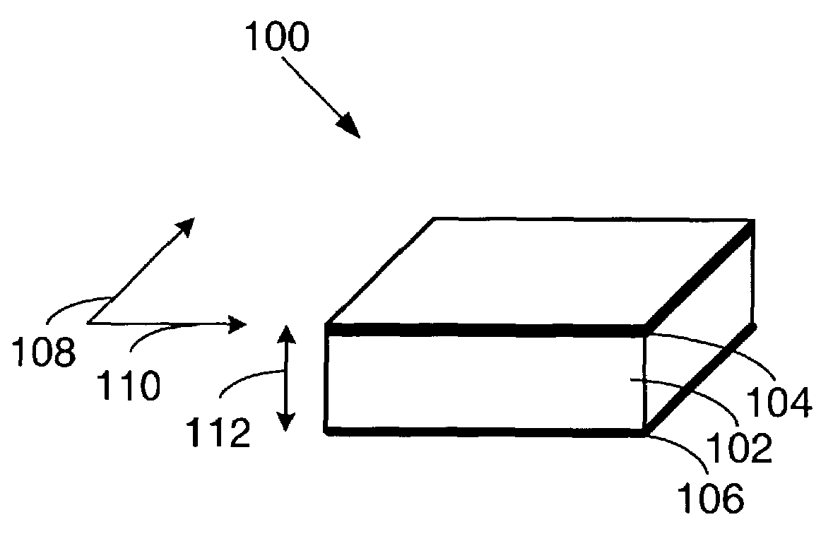
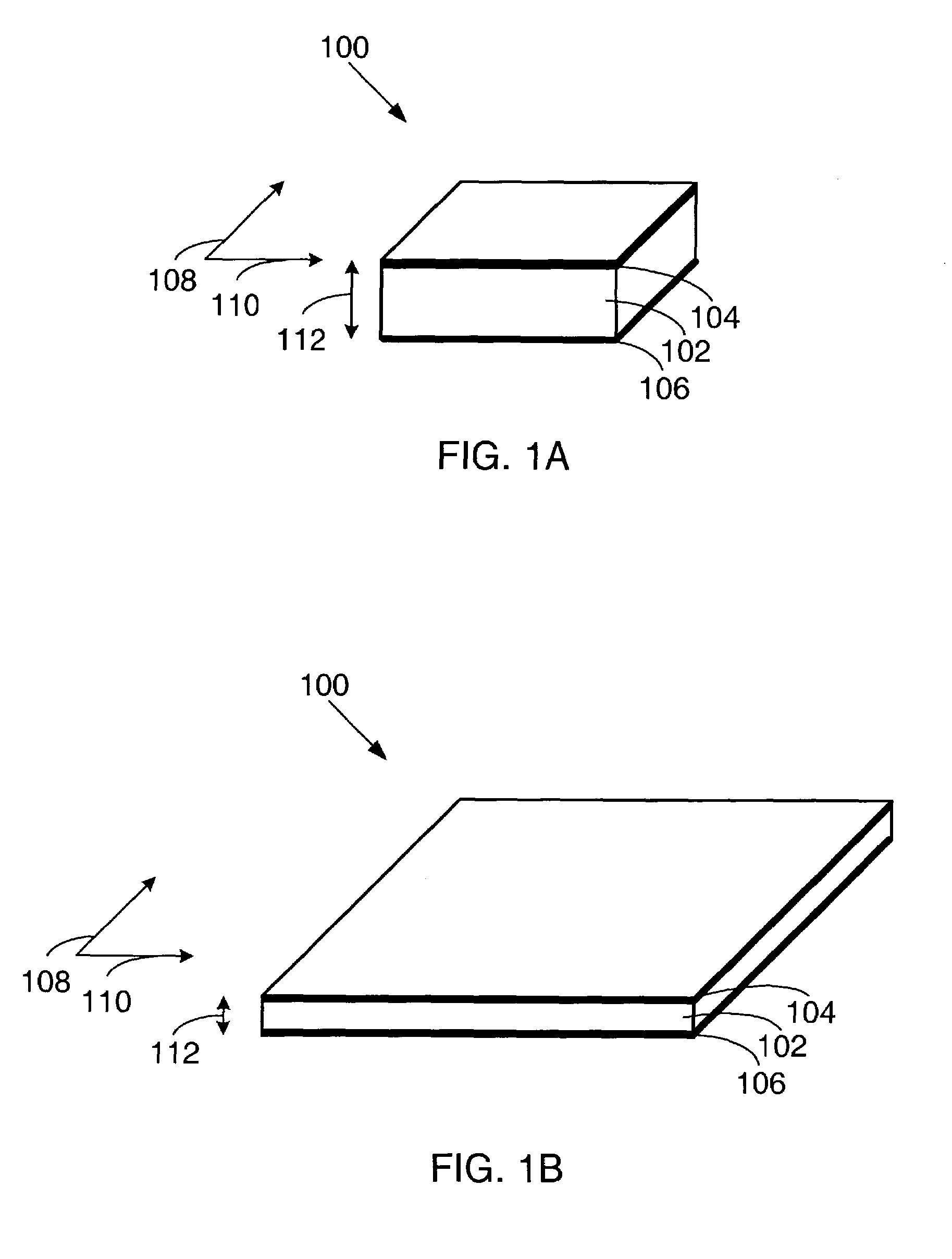
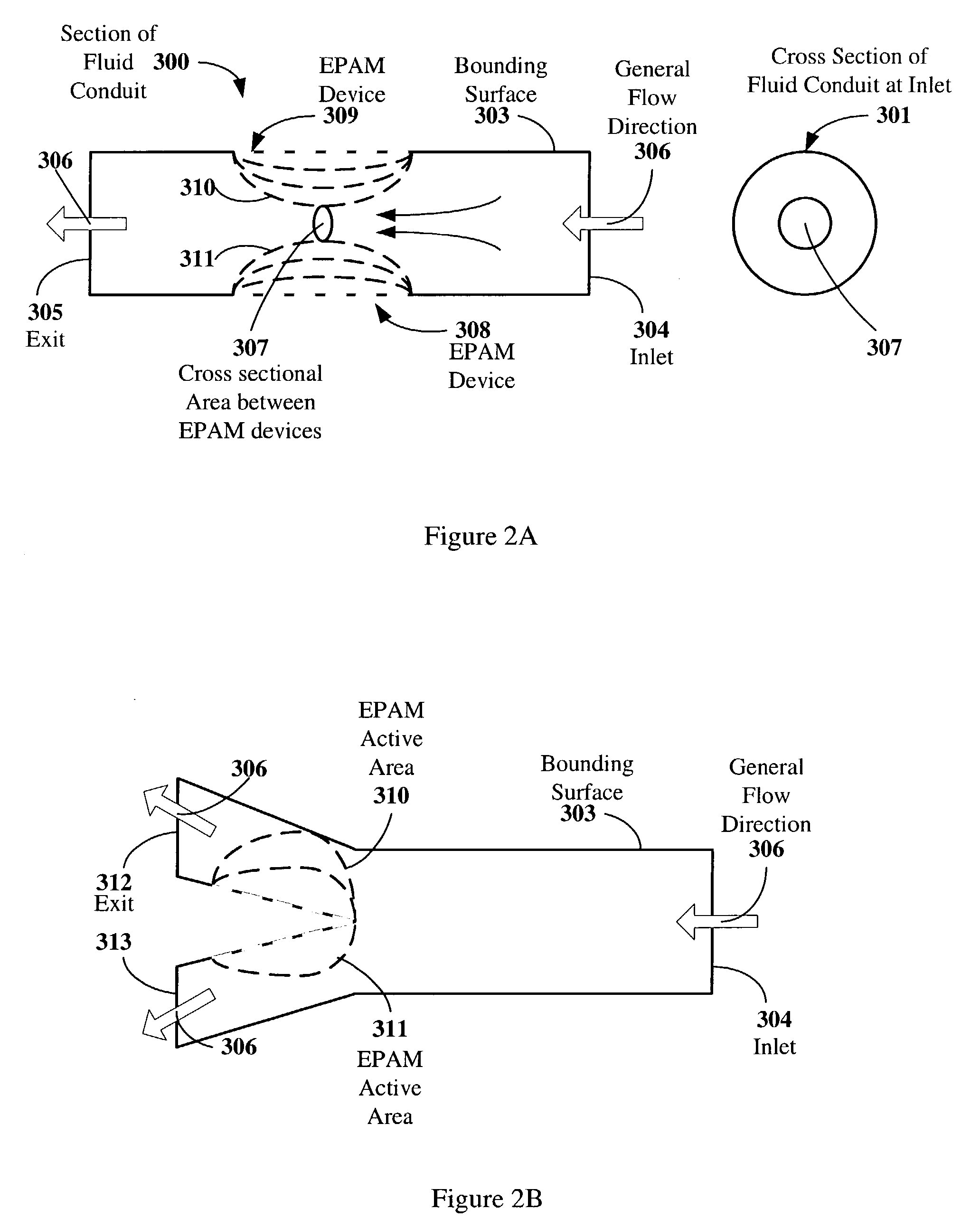
[0056]Before describing electroactive polymer (EPAM) flow control devices of the present invention, the basic principles of electroactive polymer construction and operation will first be illuminated in regards to FIG. 1A and FIG. 1B. Embodiments of flow control devices and systems of the present invention are described with respect to FIGS. 2A–2M and 3A–3M in the following section....


PUM


Abstract

The invention describes devices for controlling fluid flow, such as valves. The devices may include one or more electroactive polymer transducers with an electroactive polymer that deflects in response to an application of an electric field. The electroactive polymer may be in contact with a fluid where the deflection of the electroactive polymer may be used to change a characteristic of the fluid. Some of the characteristic of the fluid that may be changed include but are not limited to 1) a flow rate, 2) a flow direction, 3) a flow vorticity, 4) a flow momentum, 5) a flow mixing rate, 6) a flow turbulence rate, 7) a flow energy, 8) a flow thermodynamic property. The electroactive polymer may be a portion of a surface of a structure that is immersed in an external fluid flow, such as the surface of an airplane wing or the electroactive polymer may be a portion of a surface of a structure used in an internal flow, such as a bounding surface of a fluid conduit.

Description

CROSS-REFERENCE TO RELATED APPLICATION[0001]This application claims priority under 35 U.S.C. §119(e) from co-pending U.S. Provisional Patent Application No. 60 / 362,560 filed on Mar. 5, 2002, by Heim, et al. and entitled, “Electroactive Polymer Devices for Controlling Fluid Flow,” which is incorporated by reference for all purposes;[0002]and this application is a continuation-in-part and claims priority from U.S. patent application Ser. No. 09 / 792,431 entitled “Electroactive Polymer Thermal Electric Generators,” filed Feb. 23, 2001, which is incorporated herein by reference in its entirety for all purposes which claims priority under 35 U.S.C. §119(e) from U.S. Provisional Patent Application No. 60 / 184,217 filed Feb. 23, 2000, naming Q. Pei et al. as inventors, and titled “ELECTROELASTOMERS AND THEIR USE FOR POWER GENERATION”, which is incorporated by reference herein for all purposes and which also claims priority under 35 U.S.C. §119(e) from U.S. Provisional Patent Application No. ...

Claims


Application Information

Patent Timeline
Patent Type & Authority Patents(United States)
IPC IPC(8): F16K31/02F04B35/04F04B43/04H02N2/04H04R5/02H04R17/00H04R17/08H04R19/02H04R23/00
CPCF04B35/045F04B43/043H04R5/02H04R17/005H04R19/02F02G2243/52H04R17/08H04R23/00H04R2499/13
Inventor HEIM, JONATHON R.PELRINE, RONALD E.KORNBLUH, ROY DAVIDECKERLE, JOSEPH S.ROSENTHAL, MARCUSHEYDT, RICHARD P.
Owner SRI INTERNATIONAL
Why Eureka
Try Eureka